Removal Procedure
Caution: Avoid taking the following actions when you service wheel brake parts:
| • | Do not grind brake linings. |
| • | Do not sand brake linings. |
| • | Do not clean wheel brake parts with a dry brush or with compressed air. |
- Siphon 2/3 of the fluid from the master cylinder reservoir.
- Raise and support the vehicle. Refer to
Lifting and Jacking the Vehicle
in General Information.
- Remove the tire and wheel assembly from the vehicle. Refer to
Tire and Wheel Removal and Installation
in Tires
and Wheels.
- Press in the piston until the piston bottoms in its bore.

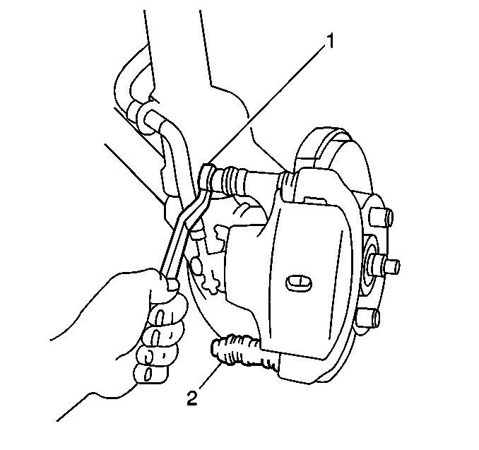
- Remove the 2 caliper
pin bolts (1,2).

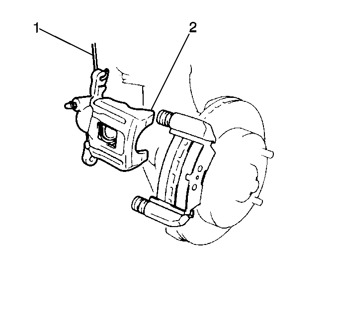
Notice: Do not allow the brake components to hang from the flexible
brake hoses. Damage to the brake hoses could result.
- Remove the caliper assembly (2) from the caliper carrier. Suspend
the caliper with a wire (1) in order to prevent damage to the brake
hose.

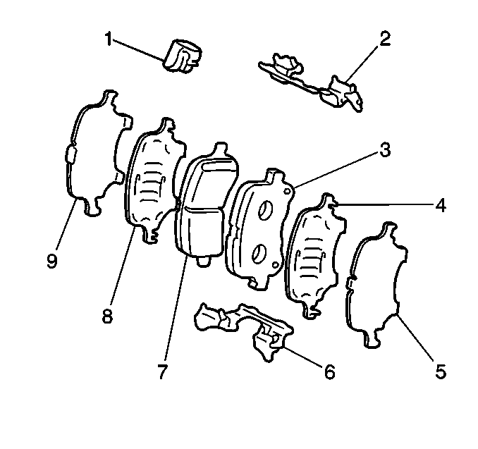
- Remove the following components
from the caliper:
| • | The pad wear indicator (1) |
| • | The 2 inner pad insulators (8,9) |
| • | The 2 outer pad insulators (4,5) |
| • | The inner brake pad (7) |
| • | The outer brake pad (3) |
| • | The 2 brake pad retainers (2,6) |

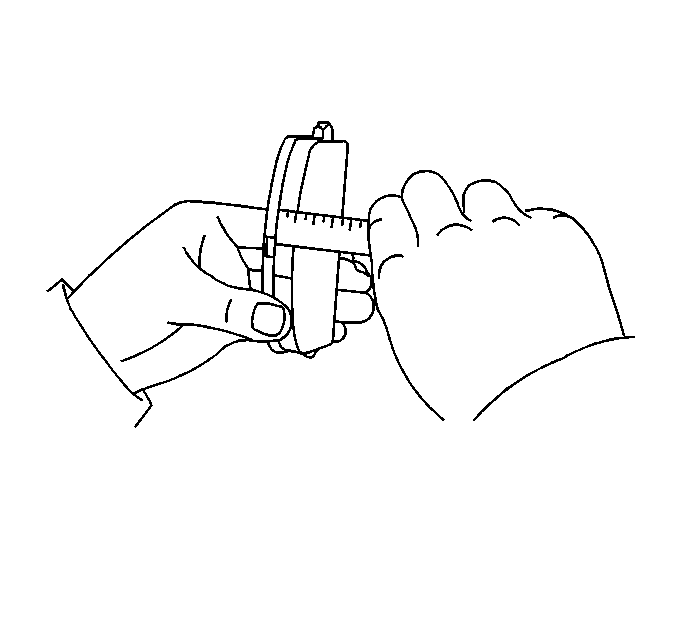
- Inspect the brake pads
for wear. If the pad thickness is less than specification, replace the disc
brake pads in axle sets.
Specification
The minimum brake pad lining thickness is 1 mm (0.039 in).
- Inspect the 2 brake pad retainers for the following conditions:
| • | If the retainers meet the above conditions, the retainers can be used
again. |
Installation Procedure

- Install the 2 brake
pad retainers (2,6) to the caliper.
- Install the front brake wear indicator (1) to the inner
pad (7).
- Apply Lubriplate® Lubricant, GM P/N 12346293, or an
equivalent lubricant meeting the requirements of NLGI #2 Category LB
or GC-LB to both sides of a new inner pad insulator (8).
- Install the inner pad insulator (8) to the inner pad (7).
- Install the inner pad insulator (9) to the inner pad insulator (8).
- Apply Lubriplate® Lubricant, GM P/N 12346293, or an
equivalent lubricant meeting the requirements of NLGI #2 Category LB
or GC-LB to both sides of a new outer pad insulator (4).
- Install the outer pad insulator (4) to the outer pad (3).
- Install the outer pad insulator (5) to the outer pad insulator (4).
- Install the inner brake pad (7) to the caliper with the
wear indicator (1) facing upward.
- Install the outer brake pad (3) to the caliper.
- Install the caliper housing to the caliper bracket.
- Apply Lubriplate® Lubricant, GM P/N 12346293, or an
equivalent lubricant meeting the requirements of NLGI #2 Category LB
or GC-LB to the caliper pin bolts.

Notice: Use the correct fastener in the correct location. Replacement fasteners
must be the correct part number for that application. Fasteners requiring
replacement or fasteners requiring the use of thread locking compound or sealant
are identified in the service procedure. Do not use paints, lubricants, or
corrosion inhibitors on fasteners or fastener joint surfaces unless specified.
These coatings affect fastener torque and joint clamping force and may damage
the fastener. Use the correct tightening sequence and specifications when
installing fasteners in order to avoid damage to parts and systems.
- Install the 2 caliper
pin bolts (1).
Tighten
Tighten the caliper pin bolts to 34 N·m (25 lb ft).
- Install the tire and wheel assembly to the vehicle. Refer to
Tire and Wheel Removal and Installation
in Tires
and Wheels.
- Lower the vehicle.
- Fill the master cylinder fluid reservoir. Refer to
Master Cylinder Reservoir Filling
in Hydraulic
Brakes.
- Burnish the pads and the rotors. Refer to
Brake Pad and Rotor Burnishing
.


