Removal Procedure
- Install the Engine Support Fixture. Refer to Engine Support Fixture in Engine Mechanical-1.8 L.
- Raise and support the vehicle. Refer to Lifting and Jacking the Vehicle in General Information.
- Remove the front tire and wheel assembly from the vehicle. Refer to Tire and Wheel Removal and Installation in Tires and Wheels.
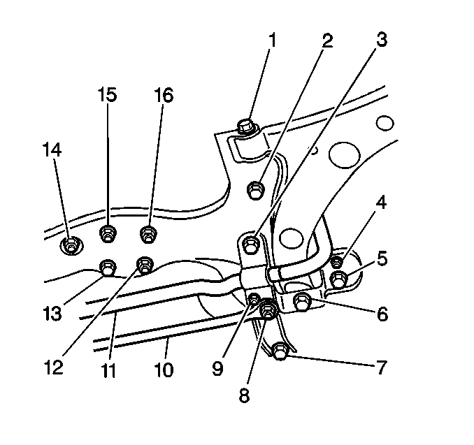
- Remove the 3 nuts (12, 15, 16) from the crossmember.
- Support the crossmember with a jack.
- Remove the following components from the bracket studs (3, 7):
- Remove the following components from the left control arm:
- Remove the following components from the right control arm:
- Remove the following components from the right side of the vehicle:
- Remove the following components from the left side of the vehicle:
- Remove the 2 bolts (5, 10) that retain the 2 engine splash shields to the trans support (6).
- Remove the 2 bolts (3, 4) that retain the front transaxle mount to the trans support.
- Remove the 2 bolts (1, 2) that retain the trans support to the vehicle.
- Lower the jack in order to remove the following components together as a unit:
- If the vehicle has a front stabilizer shaft, remove the nut (5) and the stabilizer shaft insulator clamp from the right side of the crossmember.
- Remove the nut (12) and the control arm bracket (10) from the right side of the crossmember.
- If the vehicle has a front stabilizer shaft, remove the 2 nuts in order to separate the stabilizer shaft links from the control arms.
- Remove the bolt (1) and the front control arm from the right side of the crossmember.
- If the vehicle has a stabilizer shaft, remove the nut (9) and the stabilizer shaft insulator clamp from the left side of the crossmember.
- Remove the nut (4) and the control arm bracket from the left side of the crossmember.
- Remove the bolt (1) and the front control arm from the left side of the crossmember.
- Remove the bolt (13) from the crossmember.
- Remove the nut (14) and the trans support from the crossmember.
Important: If you are removing the front suspension crossmember in order to gain access to other components, you may remove the front suspension crossmember, the trans support, the 2 lower control arms, and the front stabilizer shaft together as a complete unit.
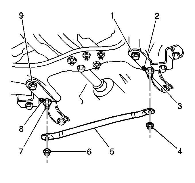
| • | The 2 nuts (4, 6) |
| • | The front suspension crossmember brace (5) |
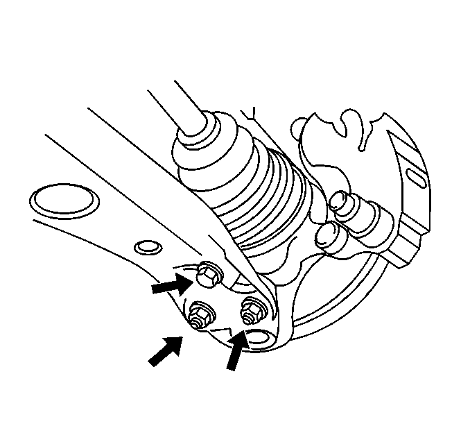
| • | The bolt |
| • | The 2 nuts |
| • | The bolt |
| • | The 2 nuts |
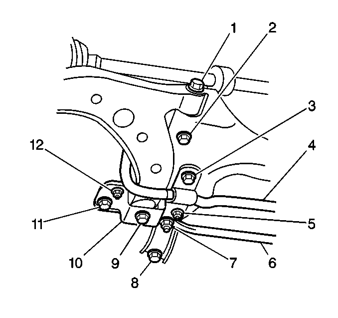
| • | The 5 bolts (2, 3, 8, 9, 11) |
| • | The stud (7) |

| • | The 5 bolts (2, 3, 5, 6, 7) |
| • | The stud (8) |
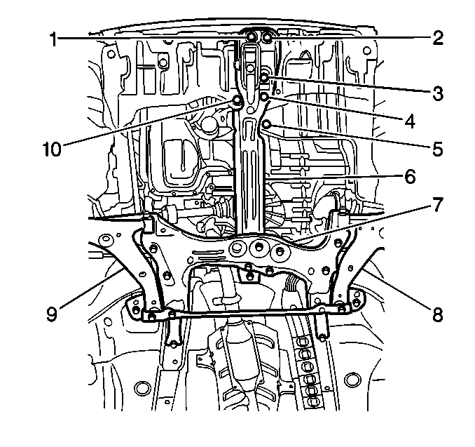
| • | The front suspension crossmember (7) |
| • | The trans support (6) |
| • | The 2 front control arms (8, 9) |
| • | The front stabilizer shaft, if the vehicle has a front stabilizer shaft |

Important: If you are replacing the front suspension crossmember or the front control arms, continue with this procedure.

Installation Procedure
- Install the trans support to the front suspension crossmember. Secure the trans support to the crossmember with the nut (14) and the bolt (13).
- Install the front control arm to the left side of the crossmember. Secure the control arm to the crossmember with the bolt (1). DO NOT tighten the bolt.
- If the vehicle has a stabilizer shaft, install the stabilizer shaft link to the left front control arm. Secure the link to the control arm with the nut. DO NOT tighten the nut.
- Install the front control arm bracket to the left side of the crossmember. Secure the bracket to the crossmember with the nut (4).
- If the vehicle has a stabilizer shaft, install the front stabilizer shaft insulator clamp to the left side of the crossmember. Secure the clamp to the crossmember with the nut (9).
- Install the front control arm to the right side of the crossmember. Secure the control arm to the crossmember with the bolt (1). DO NOT tighten bolt.
- If the vehicle has a front stabilizer shaft, install the stabilizer shaft link to the right front control arm. Secure the link to the control arm with the nut. DO NOT tighten the nut.
- Install the front control arm bracket (10) to the right side of the crossmember. Secure the bracket to the crossmember with the nut (12).
- If the vehicle has a front stabilizer shaft, install the stabilizer shaft insulator clamp to the right side of the crossmember. Secure the clamp to the crossmember with the nut (5).
- Use a jack in order to raise and support the following components together as a unit:
- Install the 2 bolts (1, 2) that secure the trans support to the vehicle. DO NOT tighten the bolts.
- Install the 2 bolts (3, 4) that secure the front transaxle mount to the trans support.
- Install the 2 engine splash shield bolts (5, 10) that secure the 2 engine splash shields to the trans support.
- Install the 2 studs (3, 7) to the bracket.
- Install the 5 bolts (2, 3, 5, 6, 7) on the left side of the vehicle. DO NOT tighten the bolts.
- Install the 5 bolts (2, 3, 8, 9, 11) on the right side of the vehicle. DO NOT tighten the bolts.
- Install the following to the right front control arm:
- Install the following to the left front control arm:
- Remove the jack from the crossmember.
- Install the 3 nuts (12, 15, 16) to the crossmember.
- Install the following components to the bracket studs (3, 7):
- Install the tire and wheel assembly. Refer to Tire and Wheel Removal and Installation in Tires and Wheels.
- Lower the vehicle.
- Raise the vehicle on a drive-on lift or on an alignment rack. Refer to Lifting and Jacking the Vehicle in General Information.
- Push down the front bumper 3 times in order to stabilize the suspension.
- Torque the 2 bolts (1, 2) that secure the trans support to the vehicle.
- Torque the inner bolt (6) that secures the left control arm and the bracket to the vehicle.
- Torque the front bolt (1) that secures the left control arm to the crossmember.
- Torque the front bolt (2) that secures the crossmember to the vehicle.
- Torque the front bolt (3) that secures the bracket to the vehicle.
- Torque the outer bolt (5) that secures the bracket to the vehicle.
- Torque the rear bolt (7) that secures the bracket to the vehicle.
- If the vehicle has a front stabilizer shaft, use a 5 mm hex wrench in order to hold the left stabilizer shaft link stud. Tighten the nut to the stabilizer shaft link stud.
- Torque the inner bolt (9) that secures the control arm and the bracket to the right side of the vehicle.
- Torque the front bolt (1) that secures the control arm to the right side of the crossmember.
- Torque the front bolt (2) that secures the crossmember to the vehicle.
- Torque the front bolt (3) that secures the bracket to the vehicle.
- Torque the outer bolt (11) that secures the bracket to the right side of the vehicle.
- Torque the rear bolt (8) that secures the bracket to the right side of the vehicle.
- If the vehicle has a front stabilizer shaft, use a 5 mm hex wrench in order to hold the right stabilizer shaft link stud. Tighten the nut to the stabilizer shaft link stud.
- Lower the vehicle.
- Remove the Engine Support Fixture. Refer to Engine Support Fixture in Engine Mechanical-1.8 L.
- Measure the wheel alignment. Adjust the wheel alignment, if necessary. Refer to Wheel Alignment Measurement in Wheel Alignment.
Notice: Use the correct fastener in the correct location. Replacement fasteners must be the correct part number for that application. Fasteners requiring replacement or fasteners requiring the use of thread locking compound or sealant are identified in the service procedure. Do not use paints, lubricants, or corrosion inhibitors on fasteners or fastener joint surfaces unless specified. These coatings affect fastener torque and joint clamping force and may damage the fastener. Use the correct tightening sequence and specifications when installing fasteners in order to avoid damage to parts and systems.

Tighten
Tighten the nut and the bolt to 60 N·m (45 lb ft).
Tighten
Tighten the nut to 19 N·m (14 lb ft).
Tighten
Tighten the nut to 19 N·m (14 lb ft).

Tighten
Tighten the nut to 19 N·m (14 lb ft).
Tighten
Tighten the nut to 19 N·m (14 lb ft).

| • | The front suspension crossmember (7) |
| • | The trans support (6) |
| • | The 2 front control arms (8, 9) |
| • | The front stabilizer shaft, if the vehicle has a front stabilizer shaft |
Tighten
Tighten the 2 front transaxle mount bolts to 64 N·m
(47 lb ft).
Tighten
Tighten the 2 splash shield bolts to 10 N·m (89 lb in).

Tighten
Tighten the 2 studs to 147 N·m (109 lb ft).


| • | The 2 nuts |
| • | The bolt |
Tighten
Tighten the 2 nuts and the bolt to 142 N·m (105 lb ft).
| • | The 2 nuts |
| • | The bolt |
Tighten
Tighten the 2 nuts and the bolt to 142 N·m (105 lb ft).

Tighten
Tighten the nuts to 57 N·m (42 lb ft).

| • | The front suspension crossmember brace (5) |
| • | The 2 nuts (4, 6) |
Tighten
Tighten the 2 nuts to 69 N·m (51 lb ft).
Important: The weight of the vehicle must be on the vehicle's tires.

Tighten
Tighten the 2 bolts to 60 N·m (45 lb ft).

Tighten
Tighten the bolt to 175 N·m (129 lb ft).
Tighten
Tighten the bolt to 215 N·m (158 lb ft).
Tighten
Tighten the bolt to 225 N·m (167 lb ft).
Tighten
Tighten the bolt to 225 N·m (167 lb ft).
Tighten
Tighten the bolt to 147 N·m (109 lb ft).
Tighten
Tighten the bolt to 123 N·m (91 lb ft).
Tighten
Tighten the nut to 44 N·m (33 lb ft).

Tighten
Tighten the bolt to 175 N·m (129 lb ft).
Tighten
Tighten the bolt to 215 N·m (158 lb ft).
Tighten
Tighten the 2 bolts to 225 N·m (167 lb ft).
Tighten
Tighten the 2 bolts to 225 N·m (167 lb ft).
Tighten
Tighten the bolt to 147 N·m (109 lb ft).
Tighten
Tighten the bolt to 123 N·m (91 lb ft).
Tighten
Tighten the nut to 44 N·m (33 lb ft).
