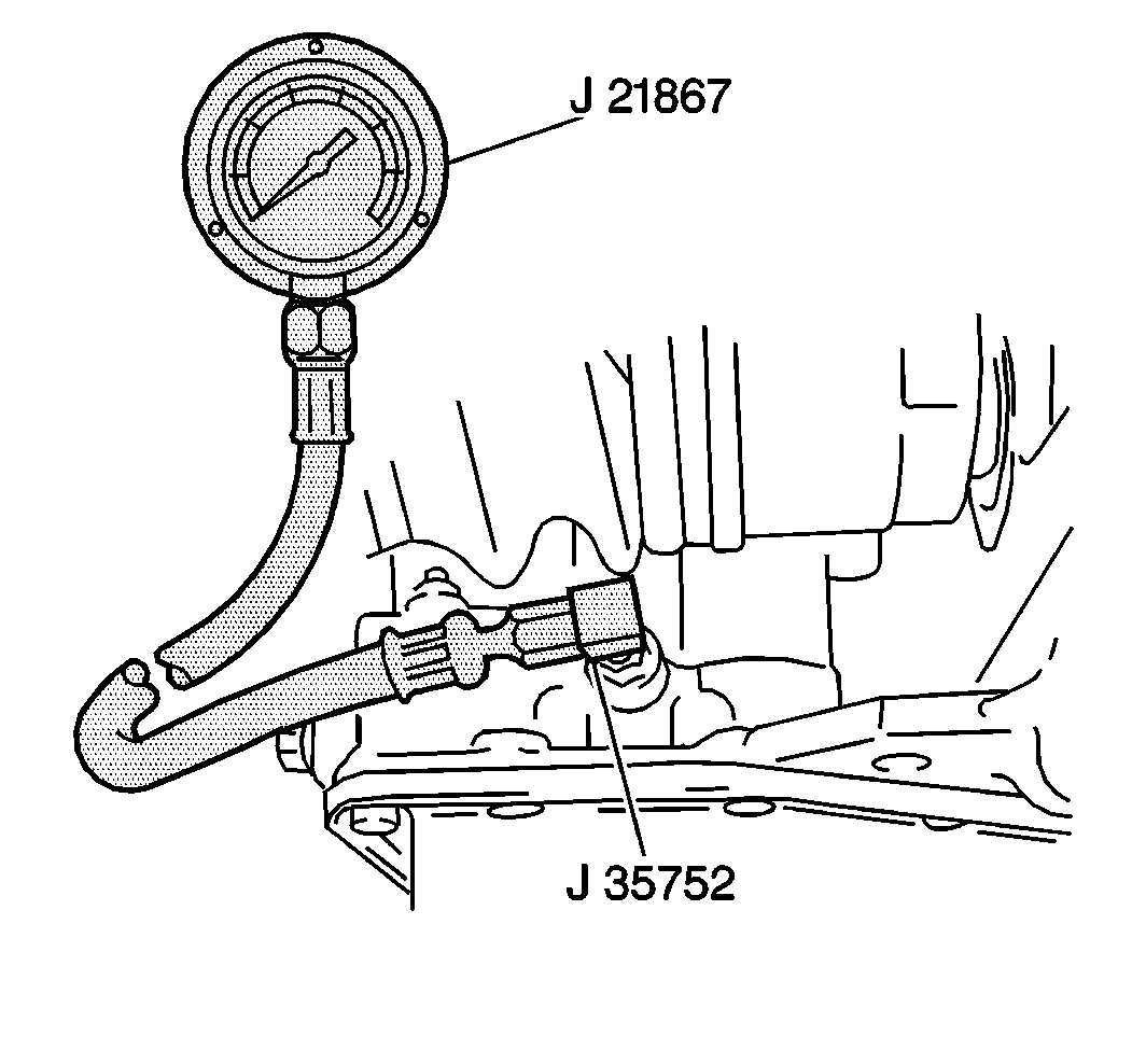
Tools Required
| • | J 35752 Oil
Pressure Gage Adapter |
| • | J 21867 Universal
Pressure Gage Set |
Important: Perform this test only at a normal operating fluid temperature of 50-80°C
(122-176°F).
- Raise the vehicle. Support the vehicle. Refer to
Lifting and Jacking the Vehicle
in General Information.
- Remove 6 bolts and left splash shield from vehicle.
- Remove the left splash shield.

- Remove the pressure tap
bolt from the rear of the transaxle.
- Install J 35752
into the line pressure tap at the rear of the transaxle.
- Install J 21867
into J 35752
.
- Lower the vehicle.
- Route J 21867
hose
over the front fender and through the driver's window so that it can be read
from the passenger compartment.
- Connect the scan tool to the Data Link Connector (DLC) and display
the engine RPM.
- Apply the parking brake and block the vehicle wheels.
- Press the brake pedal fully and start the engine.
- Display the engine speed (RPM) on the scan tool.
Caution: For the following four steps, procedures for testing line pressure at
idle and stall speeds, the brake pedal must be fully pressed throughout the
measurement procedure. Failure to do so could result in personal injury and/or
property damage.
- Place the manual selector in the drive (D) position and record the line
pressure at idle speed (650-750 RPM). Do the same for the (D2) position.
Notice: DO NOT run engine at stall speed for more than five seconds continuously
or engine oil and transaxle fluid temperatures may become excessively high.
- Press the accelerator pedal fully (wide open throttle) and record the
line pressure in the drive (D) position at stall speed (2,150-2,450 RPM).
Release the accelerator pedal. Do the same for the (D2) position and
record the line pressure.
- Keeping the brake pedal fully pressed, place the selector lever
in the reverse (R) position and record the line pressure at idle speed (650
to 750 RPM).
- Press the accelerator pedal fully (wide open throttle) and record
the line pressure in the reverse (R) position at stall speed (2,150-2,450 RPM).
Release the accelerator pedal.
- Keep the brake pedal fully pressed.
- Place the manual selector in Low position. Record the line pressure
at idle speed (650-750 RPM).
- Press the accelerator pedal fully (wide open throttle) and record
the line pressure in Low position at stall speed (2,150-2,450 RPM).
Release the accelerator pedal.
- Place the manual selector in Park position and turn the ignition
switch to LOCK.
- Remove the scan tool from the vehicle.
- Remove J 21867
from the passenger compartment.
- Raise and suitably support the vehicle. Refer to
Lifting and Jacking the Vehicle
in General Information.
- Remove J 21867
from J 35752
.
- Remove J 35752
from the line pressure tap at the rear of the transaxle.
Notice: Use the correct fastener in the correct location. Replacement fasteners
must be the correct part number for that application. Fasteners requiring
replacement or fasteners requiring the use of thread locking compound or sealant
are identified in the service procedure. Do not use paints, lubricants, or
corrosion inhibitors on fasteners or fastener joint surfaces unless specified.
These coatings affect fastener torque and joint clamping force and may damage
the fastener. Use the correct tightening sequence and specifications when
installing fasteners in order to avoid damage to parts and systems.
- Install the line
pressure tap bolt into the line pressure tap at the rear of the transaxle.
Tighten
Tighten the line pressure tap bolt to 9 N·m (80 lb in).
- Install the left splash shield.
- Secure with 6 bolts.
Tighten
Tighten the splash shield bolts to 5 N·m (44 lb in).
- Lower the vehicle.
Evaluation
Compare the line pressure test results with the line pressure specifications.
If the line pressure is not as specified, refer to the Line Pressure
Test Diagnosis for further evaluation.
Line Pressure Test Diagnosis
Line Pressure Measurement
| Probable Cause
|
Higher than Specification in Drive (D) and Reverse (R)
Ranges
|
| • | Pressure regulator valve malfunction |
| • | Throttle valve malfunction |
| • | Out of adjustment accelerator and/or throttle valve cable |
|
Lower than Specification in Drive (D) and Reverse (R) Ranges
|
| • | Pressure regulator valve malfunction |
| • | Throttle valve malfunction |
| • | Out of adjustment accelerator and/or throttle valve cable |
|
Lower than Specification in Drive (D) Range Only
|
| • | Forward clutch fluid circuit leak |
| • | Drive (D) range fluid circuit leak |
|
Lower than Specification
in Reverse (R) Range Only
|
| • | Direct clutch fluid circuit leak |
| • | 1st-reverse brake fluid circuit leak |
| • | Reverse (R) range fluid circuit leak |
|

