Removal Procedure
Notice: Check the resistance values of all PCM relays, solenoids, and other output controls before replacing or substituting the Powertrain Control Module (PCM). Check all the sensor wiring and the PCM output control circuits for a short to ground before replacing or substituting the PCM. Perform all circuit repairs or malfunctioning component part replacements before installing a replacement or substitute PCM. This will prevent damage to the replacement or substitute PCM.
Notice: Do not touch the connector pins or soldered components on the circuit board in order to prevent possible electrostatic discharge (ESD) damage to the PCM.
Notice: Turn the ignition OFF when installing or removing the PCM connectors and disconnecting or reconnecting the power to the PCM (battery cable, PCM pigtail, PCM fuse, jumper cables, etc.) in order to prevent internal PCM damage.
Important: Service of the powertrain control module (PCM) consists of a complete replacement of the PCM. There are no serviceable parts, such as programmable read-only memory (PROM) or erasable programmable read-only memory (EPROM) to replace inside the PCM. If the PCM is determined to be faulty, the PCM is to be replaced as a complete assembly.
- Disable the supplemental inflatable restraint (SIR) system. Refer to Disabling the SIR System in SIR.
- Disconnect the negative battery cable.
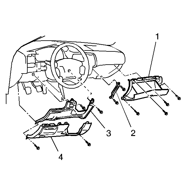
- Remove the glove box (1).
- Remove the console support bracket (2).
- Remove the left knee bolster trim panel (4).
- Remove the left knee bolster (3).
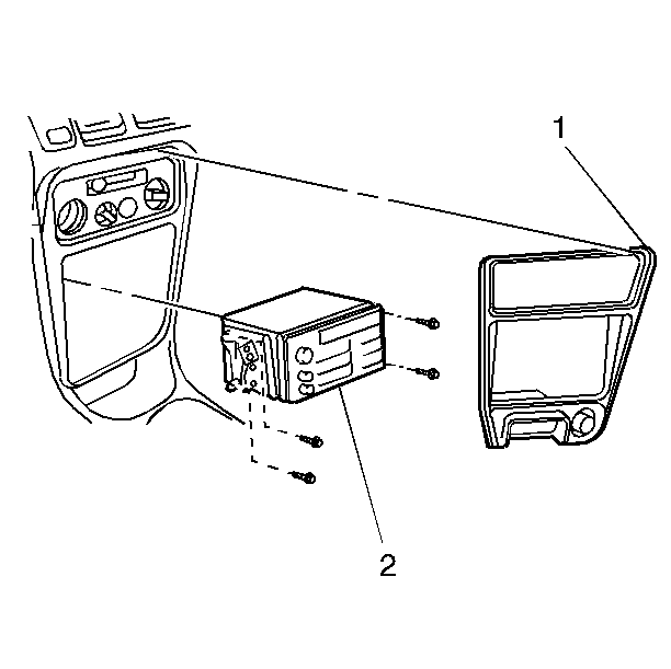
- Remove the center trim panel (1).
- Remove the radio (2), if equipped.
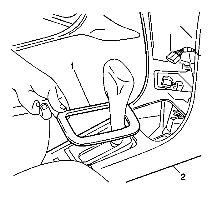
- Remove the shifter trim plate (1) from the front floor console (2) (A/T only).
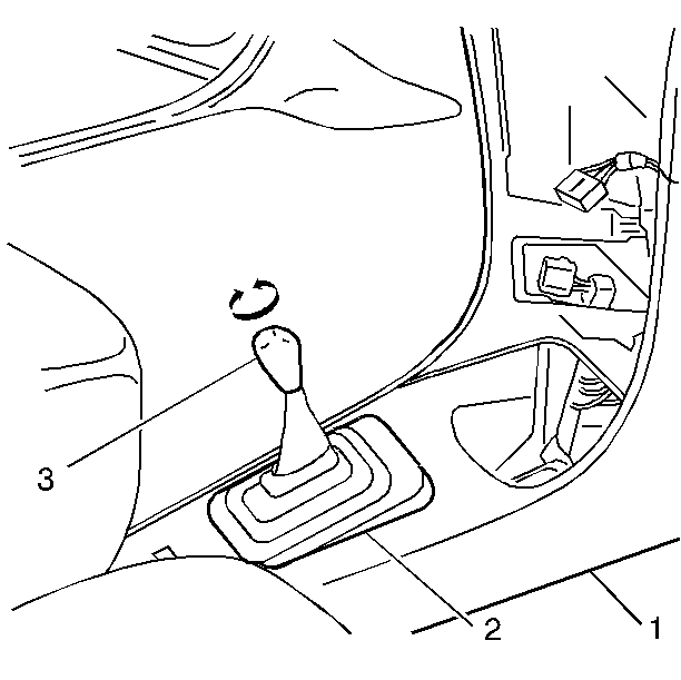
- Remove the manual shifter knob (3) and the shifter boot (2) from the shifter lever and the front floor console (1) (M/T only).
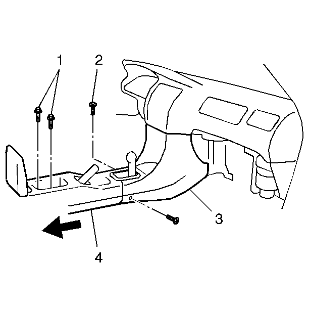
- Remove the 2 bolts in the rear console box (1).
- Remove the 2 screws on each side of the front floor console (2).
- Slide the center console back toward the rear seats (4).
- Remove the 2 upper screws of the front floor console.
- Remove the front floor console (3).
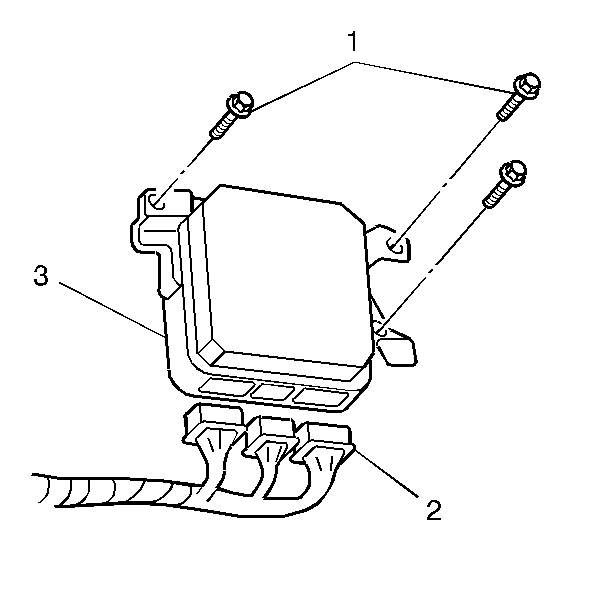
- Remove the 3 bolts (1) and the PCM (3), from the console carriage.
- Remove the 3 PCM wiring harness electrical connectors (2) from the PCM (3).
Caution: Unless directed otherwise, the ignition and start switch must be in the OFF or LOCK position, and all electrical loads must be OFF before servicing any electrical component. Disconnect the negative battery cable to prevent an electrical spark should a tool or equipment come in contact with an exposed electrical terminal. Failure to follow these precautions may result in personal injury and/or damage to the vehicle or its components.
Installation Procedure
Notice: Do not touch the connector pins or soldered components on the circuit board in order to prevent possible electrostatic discharge (ESD) damage to the PCM.
Notice: Turn the ignition OFF when installing or removing the PCM connectors and disconnecting or reconnecting the power to the PCM (battery cable, PCM pigtail, PCM fuse, jumper cables, etc.) in order to prevent internal PCM damage.
- Connect the 3 PCM wiring harness electrical connectors (2) to the PCM (3).
- Install the PCM (3) into the console carriage.
- Secure the PCM (3) with 3 bolts (1).
- Install the front floor console (3).
- Secure the upper portion of the front floor console with the 2 screws.
- Install the center console (4) to the front floor console (3).
- Secure the center console with the 2 bolts (1).
- Secure the front floor console and center console with the 2 screws (2).
- Install the shifter trim plate (1) to the front floor console (2) (A/T only).
- Install the manual shifter boot (2) over the shifter lever and secure to the front floor console (1) (M/T only).
- Install the shifter knob (3) onto the shifter lever (M/T only).
- Install the radio (2), if equipped.
- Install the center trim panel (1).
- Install the left side knee bolster (3).
- Install the left knee bolster trim panel (4).
- Install the console support bracket (2).
- Install the glove box (1).
- Connect the negative battery cable.
- Enable the supplemental inflatable restraint (SIR) system. Refer to Enabling the SIR System in SIR.

Notice: Use the correct fastener in the correct location. Replacement fasteners must be the correct part number for that application. Fasteners requiring replacement or fasteners requiring the use of thread locking compound or sealant are identified in the service procedure. Do not use paints, lubricants, or corrosion inhibitors on fasteners or fastener joint surfaces unless specified. These coatings affect fastener torque and joint clamping force and may damage the fastener. Use the correct tightening sequence and specifications when installing fasteners in order to avoid damage to parts and systems.
Tighten
Tighten the PCM bracket bolts to 15 N·m (11 lb ft).


