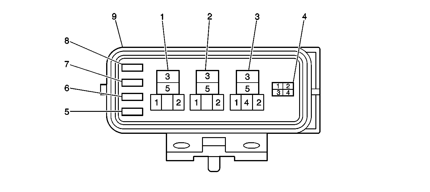
| Table 1: | Compressor Control Module Voltage Table |
Step | Action | Yes | No |
|---|---|---|---|
Schematic Reference: HVAC Schematics | |||
1 | Did you review the Air Delivery Description and Operation and the Air Temperature Description and Operation and perform the necessary inspections? | Go to Step 2 | |
2 |
Does the A/C compressor clutch engage? | Go to Testing for Intermittent Conditions and Poor Connections in Wiring Systems | Go to Step 3 |
3 |
Does the A/C compressor clutch engage? | Go to Step 15 | Go to Step 4 |
4 |
Does the test lamp illuminate? | Go to Step 16 | Go to Step 5 |
5 | Test the A/C compressor clutch ground circuit for an open. Refer to Circuit Testing and Wiring Repairs in Wiring Systems. Did you find and correct the condition? | Go to Step 21 | Go to Step 6 |
6 | Test the A/C compressor clutch supply voltage circuit for an open. Refer to Circuit Testing and Wiring Repairs in Wiring Systems. Did you find and correct the condition? | Go to Step 21 | Go to Step 7 |
7 |
Did you find and correct the condition? | Go to Step 21 | Go to Step 8 |
8 | Test the A/C MG relay control circuit for an open. Refer to Circuit Testing and Wiring Repairs in Wiring Systems. Did you find and correct the condition? | Go to Step 21 | Go to Step 9 |
9 | Test the A/C compressor control module supply voltage circuit (including the A/C switch) for an open. Refer to Circuit Testing and Wiring Repairs in Wiring Systems. Refer to Control Assembly Replacement for A/C switch replacement. Did you find and correct the condition? | Go to Step 21 | Go to Step 10 |
10 | Test the A/C compressor control module ground circuit for an open. Refer to Circuit Testing and Wiring Repairs in Wiring Systems. Did you find and correct the condition? | Go to Step 21 | Go to Step 11 |
11 | Test the A/C refrigerant pressure switch circuit and the switch for an open. Refer to Circuit Testing and Wiring Repairs in Wiring Systems and Air Conditioning (A/C) Refrigerant Pressure Sensor Replacement . Did you find and correct the condition? | Go to Step 21 | Go to Step 12 |
12 | Test for a short to ground in the BLU/WHT wire between the underhood data link connector terminal 8 (TE 1) and the PCM connector 2 terminal 15. Grounding this circuit puts the vehicle in diagnostic request mode and will prevent the A/C from operating when the engine speed is below 1200 RPM. Did you find and correct the condition? | Go to Step 21 | Go to Step 13 |
13 | Test the A/C output control circuit for an open or a short to ground. Refer to Circuit Testing and Wiring Repairs in Wiring Systems. Did you find and correct the condition? | Go to Step 21 | Go to Step 14 |
14 | Test the A/C cutout signal circuit for a short to ground. Refer to Circuit Testing and Wiring Repairs in Wiring Systems. Did you find and correct the condition? | Go to Step 21 | Go to Step 17 |
15 | Inspect for a poor connection at the fuse and relay block 2 connector of the A/C MG relay. Refer to Testing for Intermittent Conditions and Poor Connections and Connector Repairs in Wiring Systems. Did you find and correct the condition? | Go to Step 21 | Go to Step 18 |
16 | Inspect for a poor connection at the harness connector of the A/C compressor clutch. Refer to Testing for Intermittent Conditions and Poor Connections and Connector Repairs in Wiring Systems. Did you find and correct the condition? | Go to Step 21 | Go to Step 19 |
17 | Inspect for a poor connection at the harness connector of the A/C compressor control module. Refer to Testing for Intermittent Conditions and Poor Connections and Connector Repairs in Wiring Systems. Did you find and correct the condition? | Go to Step 21 | Go to Step 20 |
18 | Replace the MG relay. Refer to Compressor Relay Replacement . Did you complete the replacement? | Go to Step 21 | -- |
19 | Replace the A/C compressor clutch. Refer to Compressor Clutch Plate and Hub Assembly Removal , Air Conditioning Clutch Coil Removal , Air Conditioning Clutch Coil Installation and Compressor Clutch Plate/Hub Assembly Install . Did you complete the replacement? | Go to Step 21 | -- |
20 | Replace the A/C compressor control module. Refer to Air Conditioning (A/C) Compressor Control Module Replacement . Did you complete the replacement? | Go to Step 21 | -- |
21 | Operate the system in order to verify the repair. Did you correct the condition? | System OK | Go to Step 3 |
Terminal-Wire Color | Circuit | Normal Voltage | Condition |
|---|---|---|---|
1-YEL/BLU | Refrigerant Pressure Switch | B+ | Ignition switch ON |
2 | Not Used | ||
3-RED/BLU | A/C Cutout Signal (WOT) | 0-1 Volts | Ignition Switch ON, A/C Switch OFF |
10-14 Volts | Engine Running, A/C Operating | ||
4-WHT/BLU | Ground | 0-1 Volts | Ignition switch ON |
5-YEL | Ignition Positive Voltage | B+ | Ignition Switch ON, A/C Switch ON or Defrost Switch ON |
6-7 | Not Used | ||
8-YEL/RED | A/C ON Output Control | 10-14 Volts | Ignition Switch ON, A/C Switch OFF |
0-1 Volts | Engine Running, A/C Operating | ||
9-BLU/BLK | A/C MG Relay Control | B+ | Ignition Switch ON, A/C Switch OFF |
0-1.5 Volts | Engine Running, A/C Operating | ||
10 | Not Used | ||

