Wiper System Description
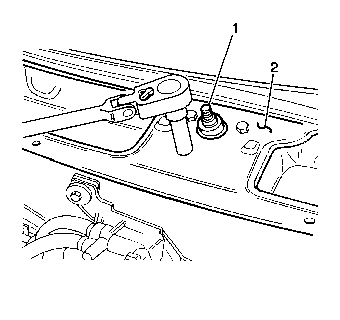
The windshield wiper system includes the following components:

| • | The wiper transmission (1) |

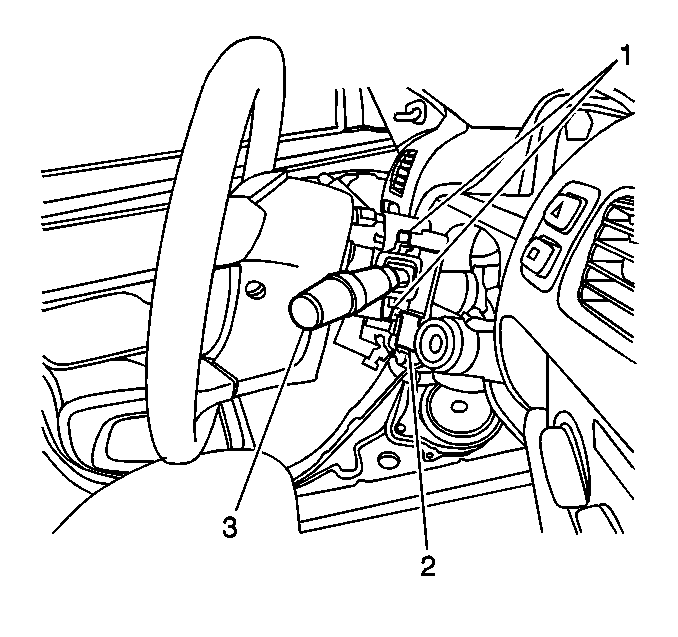
The wiper/washer switch (3) controls the wiper system. The switch is
located on the right side of the steering column. The wiper circuit ensures
that the wiper blades will automatically return to their final rest position
when the wiper switch is OFF.
Interval (Pulse) System Operation
Move the wiper/washer switch to the INT position, in order to operate
the wiper system in the intermittent (pulse) mode. With the ignition switch
in the ON position, B+ is applied to cavity 6 of the windshield wiper
motor. With the windshield wiper/washer switch in the INTERVAL position,
B+ is applied to cavity 3 of the windshield wiper motor. The length
of delay time is determined by the interval switch. Turn the ring on the wiper/washer
switch from S (slow cycling) to F (fast cycling) in order to adjust the
cycle speed. The windshield wiper motor operates the wipers for the desired
delay.
LOW Speed System Operation
With the ignition switch in the ON position, B+ is applied to cavity 6
of the windshield wiper motor. When the windshield wiper/washer switch is
in the LO position, B+ is applied to cavity 3 of the windshield wiper
motor. The windshield wiper motor operates the wipers at LOW speed until
the windshield wiper/washer switch is turned to the OFF position.
When the windshield wiper washer switch is turned off, the mechanical
pawl of the windshield wiper motor has B+ applied to cavity 5 until
it moves to the park position. In the park position an open occurs through
the windshield wiper motor cavity 6 and cavity 5, breaking
the circuit.
HIGH Speed System Operation
With the ignition switch in the ON position, B+ is applied to cavity 6
of the windshield wiper motor. When the windshield wiper/washer switch is
in the HI position, B+ is applied to cavity 2 of the windshield wiper
motor. The windshield wiper motor operates the wipers at HIGH speed until
the windshield wiper/washer switch is turned to the OFF position.
When the windshield wiper/washer switch is turned OFF, the mechanical
pawl of the windshield wiper motor has B+ applied to cavity 5 until
it moves to the park position. In the park position an open occurs through
the windshield wiper motor cavity 6 and cavity 5, breaking the circuit.
Washer System Description
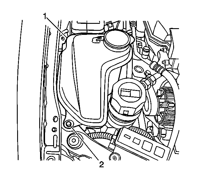
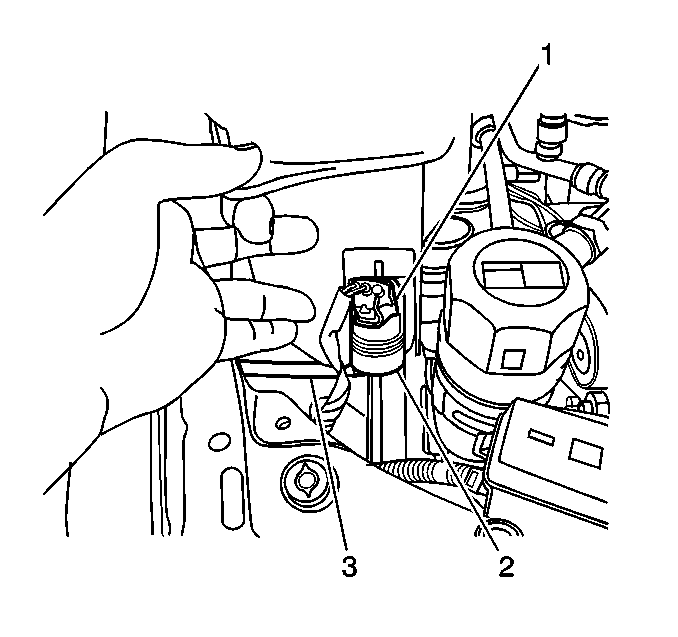
The windshield washer system includes the following components:

| • | The washer solvent container
(1) |

| • | The washer pump (1) attached
to the container |
The washer solvent container is mounted on the right fender, behind
the headlamp.
Washer System Operation

Pull the wiper/washer switch (3) in a rearward direction in order to
activate the washer system. The washer will operate until you release the
lever. When you activate the washer system, the wipers will operate at
low speed.


