Manual Bleeding
- If the vehicle has ABS and you replaced the master cylinder or
the BPMV, refer to
Antilock Brake System Automated Bleed Procedure
in
Antilock Brake System.
- Clean any dirt and foreign material from the hydraulic brake hose
and the fittings.
- Apply the brakes several times in order to remove vacuum reserve.

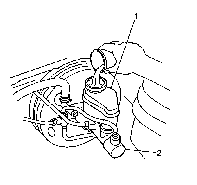
- Clean the cap for the
reservoir (1).
- Remove the cap for the reservoir (1).
- Fill the reservoir with brake fluid, GM P/N 12377967 (or
equivalent DOT 3 brake fluid) to the MAX Mark on the reservoir.
- Install the cap for the reservoir (1).
- Ensure that the level of the brake fluid in the reservoir is at
least one-half full during the bleeding operation.
Important: Bleed the wheel cylinder or calipers in the following sequence:
- Right rear
- Left rear
- Right front
- Left front
- Raise and support the vehicle. Refer to
Lifting and Jacking the Vehicle
in General Information.

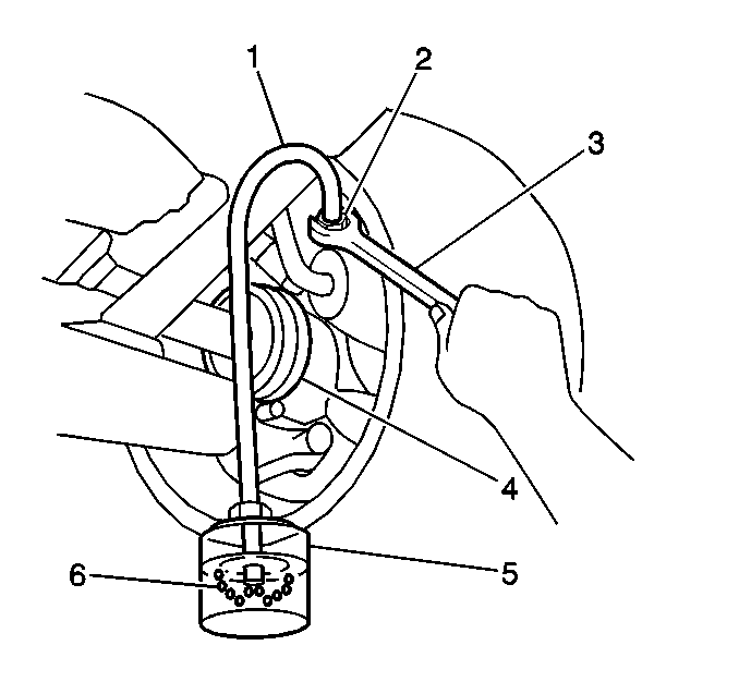
- Place a box end wrench (3)
over the bleeder valve (2).
- Attach a transparent hose (1) over the bleeder valve (2).
- Submerge the other end of the hose in a transparent container (5)
filled with brake fluid (6).
- Ask an assistant to complete the following actions:
| 13.1. | Depress the brake pedal several times. |
| 13.2. | Hold the brake pedal fully depressed. |
- Loosen the bleeder valve (2) approximately one-half turn.
The brake pedal should now fall all the way to the floor as the brake fluid
flows out of the bleeder valve and into the clear fluid container.
Notice: Use the correct fastener in the correct location. Replacement fasteners
must be the correct part number for that application. Fasteners requiring
replacement or fasteners requiring the use of thread locking compound or sealant
are identified in the service procedure. Do not use paints, lubricants, or
corrosion inhibitors on fasteners or fastener joint surfaces unless specified.
These coatings affect fastener torque and joint clamping force and may damage
the fastener. Use the correct tightening sequence and specifications when
installing fasteners in order to avoid damage to parts and systems.
- Tighten the bleeder valve (2).
Tighten
Tighten the bleeder valve to 8.3 N·m (86 lb in).
- Ask an assistant to slowly release the pedal.
- Ask an assistant to depress and release the brake pedal.
- Bleed the hydraulic brake system until the following conditions
are met:
| • | The brake pedal application does not feel spongy. |
| • | There is no air in the brake pipes or hoses. |
| • | There are no air bubbles in the clear fluid container (6). |
- Ask an assistant to depress the brake pedal several times.
- Remove the transparent hose (1) from the bleeder valve (2).
- Remove the box end wrench (3) from the bleeder valve (2).
- Repeat the hydraulic brake system bleeding procedure at each required
wheel in order to bleed the entire hydraulic brake system.
- Lower the vehicle.
Pressure Bleeding
Tools Required
J 39801 Brake Bleeder
Adapter
- If the vehicle has ABS and you replaced the master cylinder or
the BPMV, refer to
Antilock Brake System Automated Bleed Procedure
in
Antilock Brake System.

- Clean the reservoir cap.
- Fill the reservoir with brake fluid, GM P/N 12377967 (or
equivalent Dot 3 brake fluid) to the MAX mark on the reservoir (1).
- Ensure that the level of the brake fluid in the reservoir is at
least one-half full during the bleeding operation.
- Install the J 39801
to the master cylinder reservoir.
- Connect the pressure bleeder to the J 39801
.
- Raise and support the vehicle. Refer to
Lifting and Jacking the Vehicle
in General Information.
- Clean any dirt and foreign material from the hydraulic brake hose
and from the fittings.

- Place a box and wrench
(3) over the bleeder valve (2).
- Attach a transparent hose (1) over the bleeder valve (2).
- Submerge the other end of the hose in an transparent container
(5) filled with brake fluid (6).
- Charge the pressure bleeder to 140-172 kPa (20-25 psi).
- Loosen the bleeder valve (2) approximately one-half turn. The
brake pedal should now fall all the way to the floor as the brake fluid flows
out of the bleeder valve and into the clear fluid container.
Notice: Use the correct fastener in the correct location. Replacement fasteners
must be the correct part number for that application. Fasteners requiring
replacement or fasteners requiring the use of thread locking compound or sealant
are identified in the service procedure. Do not use paints, lubricants, or
corrosion inhibitors on fasteners or fastener joint surfaces unless specified.
These coatings affect fastener torque and joint clamping force and may damage
the fastener. Use the correct tightening sequence and specifications when
installing fasteners in order to avoid damage to parts and systems.
- Tighten the bleeder valve (2).
Tighten
Tighten the bleeder valve to 8.3 N·m (85.74 lb in).
- Inspect the brake pedal application.
- Bleed the hydraulic brake system until the following conditions
are met:
| • | The brake pedal application does not feel spongy. |
| • | There is no air in the brake pipes or hoses. |
| • | There are no air bubbles in the clear fluid container (6). |
- Ensure the pressure bleeder is charged to 140-172 kPa
(20-25 psi).
- Remove the transparent hose (1) from the bleeder valve (2).
- Remove the box end wrench (3) from the bleeder valve (2).
- Repeat the hydraulic brake system bleeding procedure at each required
wheel in order to bleed the entire hydraulic brake system.
- Remove the pressure bleeder.
- Install the reservoir cap.
- Lower the vehicle.


