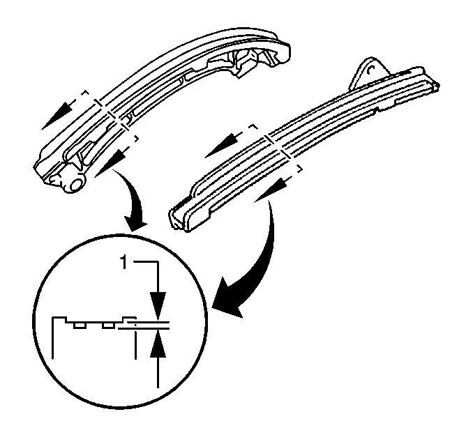
- Inspect the timing chain guides for cracking or wear.
- Replace the timing chain guides if wear exceeds 1.0 mm (0.039 in) (1).
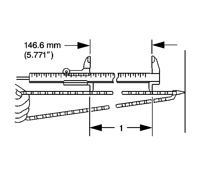
- Inspect the timing chain for elongation wear.
- Use a Vernier caliper and measure the length of 16 links with the timing chain fully stretched (1).
- If the elongation is greater than maximum, replace the timing chain.
- Inspect the camshaft and sprocket faces for signs of movement.
- Inspect the camshaft and crankshaft sprocket teeth and chain for signs of chipping or seizure of the timing chain links.
- Inspect the timing chain and timing sprockets for wear.
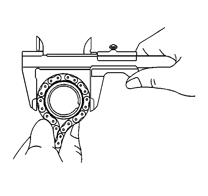
- Wrap the timing chain around each sprocket.
- Use a Vernier caliper to measure the timing sprocket diameter with the chain.
- If the diameter of any of the sprockets measured is less than the minimum, replace the timing chain and sprockets.
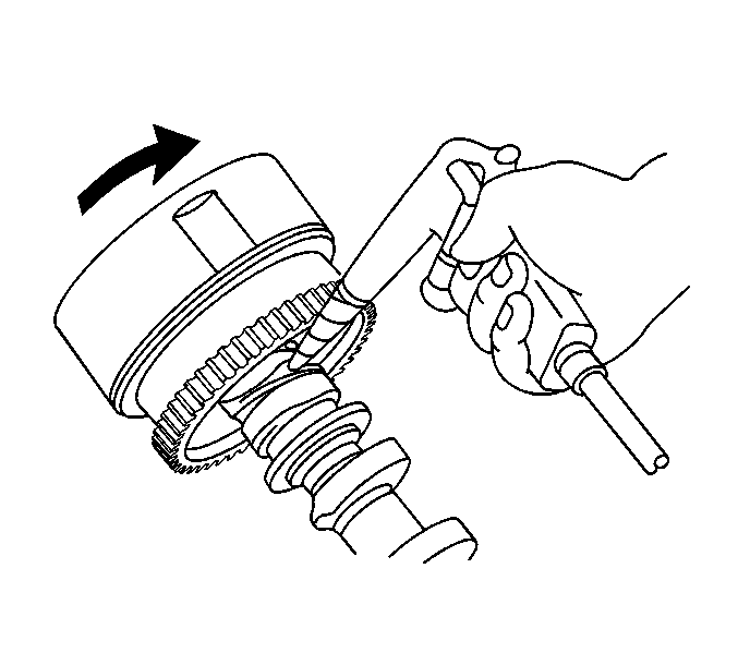
- Install the CMP actuator to the intake camshaft.
- Ensure that the CMP actuator will not turn.
- Apply air pressure of approximately 100 kPa (14 psi) to the advance passage of the camshaft.
- Turn the CMP actuator to the advanced angle side by hand.
- Rotate the actuator back and forth through the advanced positions to ensure 21 degrees of movement.
- Remove the air pressure and turn the CMP actuator back to the minimum advanced angle position to lock it.
- Replace the CMP actuator if the following conditions exist:


Maximum Chain Elongation
122.6 mm (4.827 in)
Important: Make the measurements at three or more places of the timing chain at random.

Important: Vernier calipers must contact the chain rollers for measuring.
Minimum Camshaft Sprocket Diameter With Chain
Camshaft Sprocket: 97.4 mm (3.835 in)
Minimum Crankshaft Sprocket Diameter With Chain
Crankshaft Sprocket: 51.6 mm (2.031 in)
Notice: Use the correct fastener in the correct location. Replacement fasteners must be the correct part number for that application. Fasteners requiring replacement or fasteners requiring the use of thread locking compound or sealant are identified in the service procedure. Do not use paints, lubricants, or corrosion inhibitors on fasteners or fastener joint surfaces unless specified. These coatings affect fastener torque and joint clamping force and may damage the fastener. Use the correct tightening sequence and specifications when installing fasteners in order to avoid damage to parts and systems.

Tighten
Tighten the CMP actuator bolt to 54 N·m (40 lb ft).
| • | CMP actuator does not lock with air pressure removed. |
| • | CMP actuator does not unlock with air pressure applied. |
| • | CMP actuator does not rotate smoothly through the advanced positions. |
| • | CMP actuator does not rotate completely through the advance positions. |
