- Oil the lifters and install the lifters into the lifter bores.
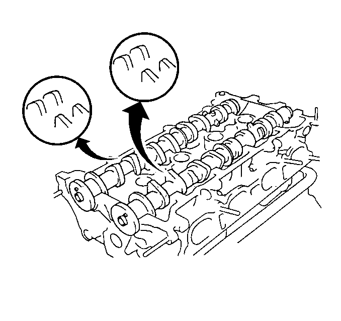
- Install the intake camshaft onto the cylinder head with the number 1 cam lobes facing as shown.
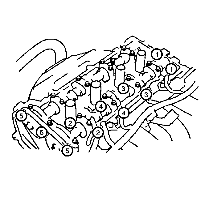
- Install the camshaft bearing caps in their proper locations with the arrows facing forward.
- Install the camshaft bearing cap bolts.
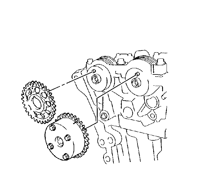
- Install the intake camshaft sprocket to the camshaft.
- Unlock the camshaft actuator locking pin. Refer to Camshaft Actuator Locking Pin Adjustment

Important: When performing any service procedure that pertains to the camshaft or the camshaft actuator, unlock the camshaft actuator locking pin. Refer to Camshaft Actuator Locking Pin Adjustment .
Important: Used lifters must be returned to the original position in the cylinder head. If the camshaft is being replaced, the lifters must also be replaced.
Important: Each bearing cap has a number and a directional arrow marked on the bearing cap.

Notice: Use the correct fastener in the correct location. Replacement fasteners must be the correct part number for that application. Fasteners requiring replacement or fasteners requiring the use of thread locking compound or sealant are identified in the service procedure. Do not use paints, lubricants, or corrosion inhibitors on fasteners or fastener joint surfaces unless specified. These coatings affect fastener torque and joint clamping force and may damage the fastener. Use the correct tightening sequence and specifications when installing fasteners in order to avoid damage to parts and systems.
Tighten
| • | Tighten the camshaft bearing cap bolts in the sequence shown to 13 N·m (10 lb ft). |
| • | Tighten the front bearing cap bolts to 23 N·m (17 lb ft). |

