PARKING BRAKE ADJUSTMENT

Model and Year: 1987-89 LLV POST OFFICE VEHICLES
Present service manuals do not contain a procedure for the adjustment of the hand lever parking brake as used on the Post Office vehicle. The following service procedure was developed to fill this need.
REQUIREMENT FOR ADJUSTMENT
The parking brake must be adjusted whenever the parking brake cables have been replaced or disconnected, or when their holding ability is not adequate. The parking brake must also be adjusted whenever the rear brakes are manually adjusted or shoes replaced.
Before adjusting the parking brakes, check the condition of the rear brakes. The rear brakes must be properly adjusted (see Section 5A2-10 in Service Manual) before proceeding with the adjustment of the parking brake.
INSPECTION OF THE PARKING BRAKE
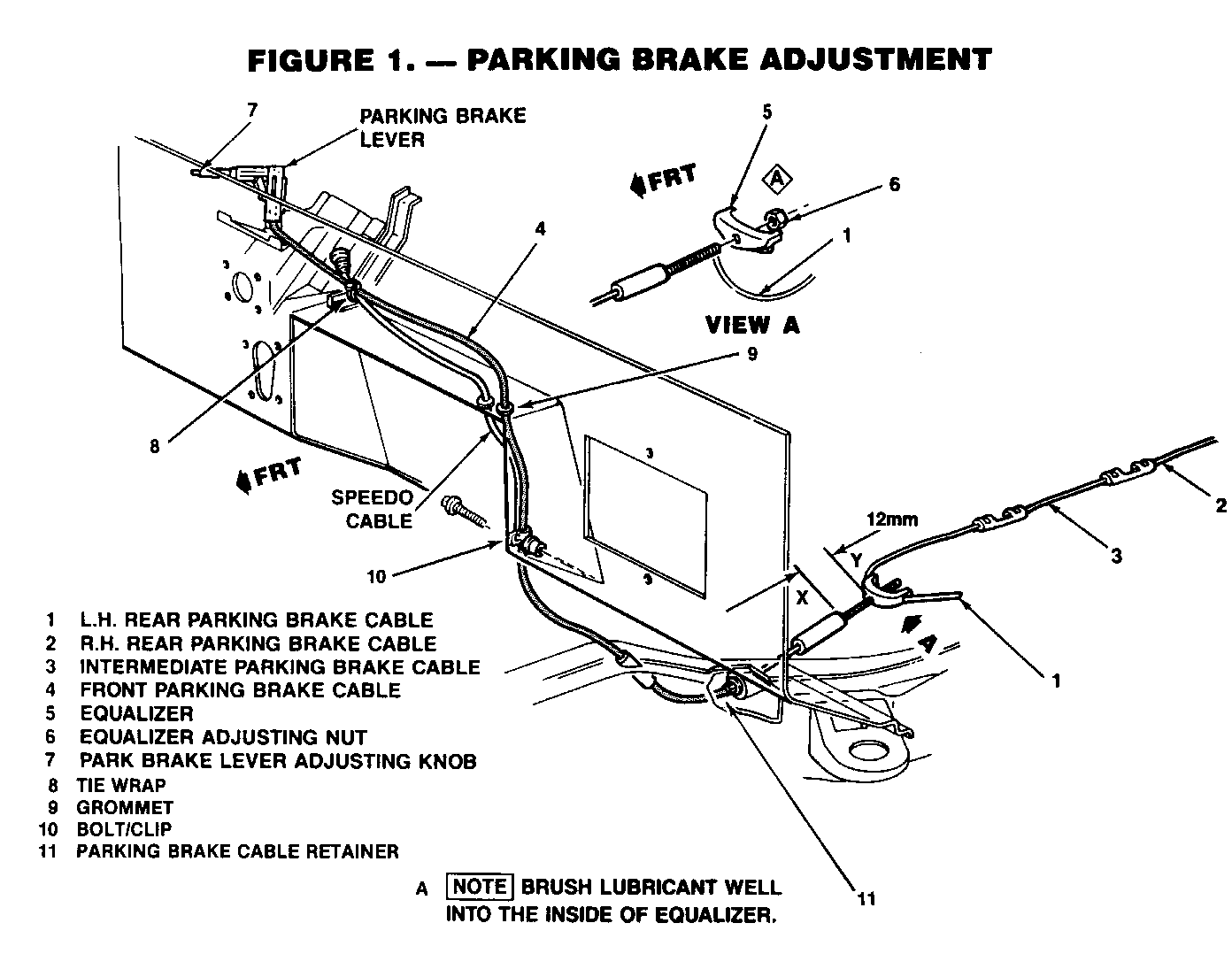
Check the parking brake system for free operation. The brake lever must return to the released position without sticking or binding. If a sticking or binding condition is present, check the cable, and cable routing for kinks or binding. Clean and lubricate the parking brake assembly and cable as necessary. (See Figure No. 1)
SERVICE PROCEDURE A (See Figure No. 1)
1. Block the front wheels.
2. Raise and support the rear axle with suitable safety stands.
3. Fully apply parking brake.
4. Remove all brake adjustment by turning adjusting knob (#7) on parking brake lever counter-clockwise until the snap-over-center, when the brake is applied, disappears.
NOTE: There may be a locking screw installed on the adjusting knob, by the Post Office, which will need to be removed prior to adjusting.)
Begin the brake adjustment with the lever in the applied position, continue to turn the knob counter-clockwise until the brake lever starts to move forward.
5. Turn parking brake knob (#7) one full turn clockwise.
6. Make certain handbrake is still in fully applied position.
7. Adjust equalizer nut(#6) using one of two methods:
A. Preferred Method
Using a Kent-Moore cable tension gage P/N J34651-A or a Burroughs Cable Tension Gage, P/N BT3375-W, installed on the right hand intermediate cable between its connecting links, tighten the equalizer nut (#6) to obtain 75-80 inch lbs. (Kent-Moore) or 150 lbs. (Burroughs) cable tension.
B. Alternate Method
Tighten the equalizer nut (#6) until a light drag is felt while rotating the rear wheels forward.
Adjust knob (#7) on parking brake lever clockwise until a definite snap over center is felt when parking brake is applied.
8. Inspection of Front Cable Thread Adjustment:
With the cable system fully adjusted, there should be a minimum of 12mm (1/2 inch) of thread available between points X and Y. If less than 12mm (1/2 inch) see Procedure B.
9. If new parking brake cables have been installed, release and fully apply the hand brake lever three times to obtain cable pre-stretch. Re-adjust equalizer nut (#6) and brake lever knob (#7) as necessary.
10. Release brake lever and rotate rear wheels forward. There should be no brake drag.
11. Remove safety stand, lower vehicle, and remove blocks from front wheels.
PARTS REOUIRED
No service parts are required for this adjustment procedure. Labor Time to perform this procedure is .3 hour. Use Labor Op: H2800.
Service Procedure B
To obtain adequate parking brake holding ability, the distance between X and Y should be a minimum of 12mm (1/2 inch). If this distance is less than 12mm (1/2 inch) the front parking brake cable #4 should be replaced.
Removal
1. Disconnect battery.
2. Remove locking screw in adjusting knob (if equipped).
3. With the parking brake lever in the full apply position, remove all adjustment by rotating knob (#7 Figure 1) on the parking brake lever counter clockwise until the "snap-over-center", when the brake is applied, disappears.
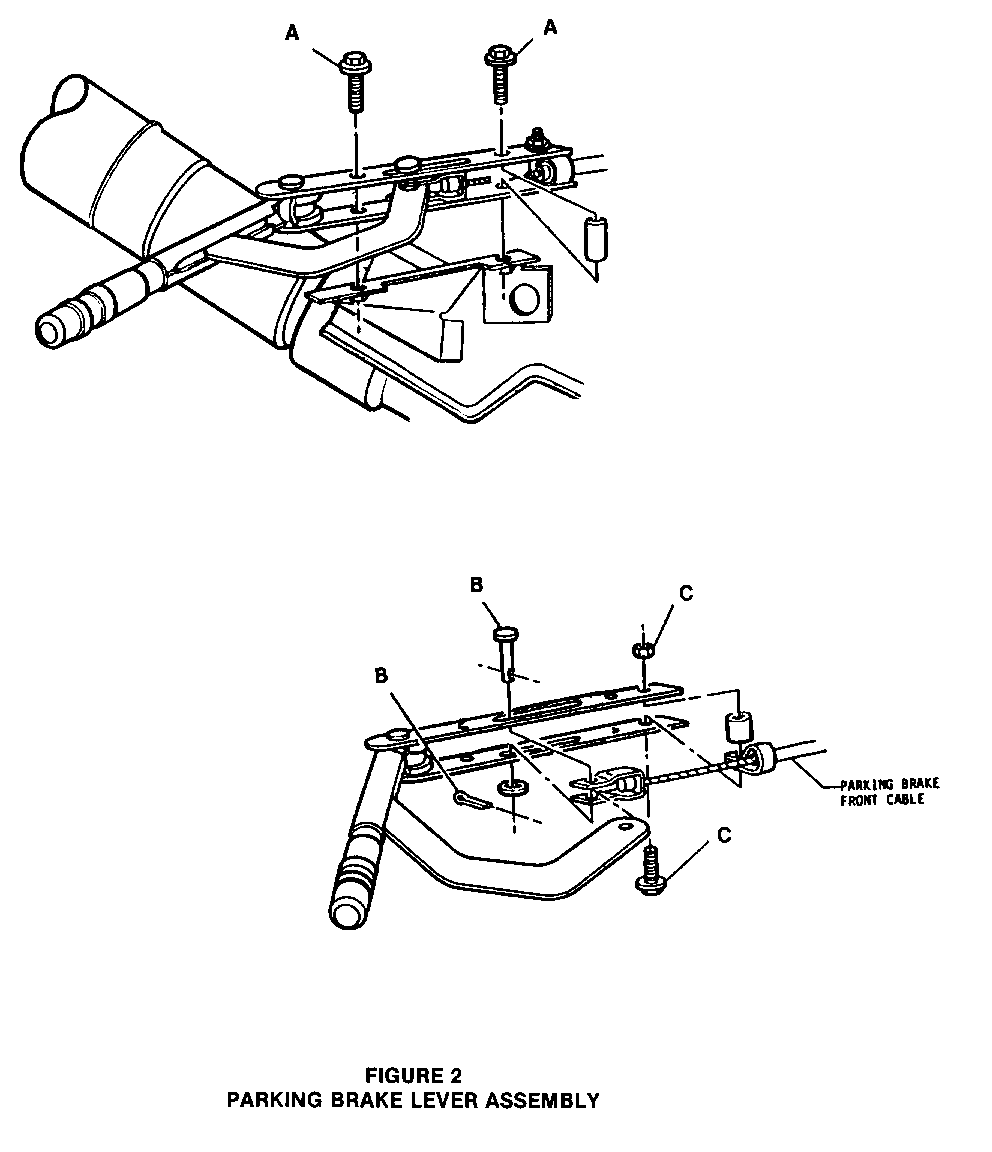
4. Remove two bolts (A Figure 2) attaching parking brake lever to the steering column. Disconnect parking brake switch wires from lever.
5. Remove cotter key and pin (B Figure 2) attaching the cable to the parking brake lever.
6. Remove bolt/nut (C Figure 2) that attaches the cable to the parking brake lever.
7. Remove tie strap (#8 Figure 1).
8. Remove six screws and dash panel cover.
9. Remove hood latch cable as follows for access to brake cable:
A. Remove hood cable mounting nut and hood knob locking nut at dash.
B. Remove hood knob.
C. Pull hood cable from engine compartment and move brake cable free from under hood latch cable.
10. Remove parking brake cable grommet (#9 Figure 1).
11. Remove bolt & clamp (#10 Figure 1) in engine compartment.
12. Raise vehicle.
13. Pinch parking brake cable retainer ears (#ll Figure 1) inward.
14. Pull cable out of frame.
15. Lower vehicle and remove parking brake cable.
Installation
1. Route new parking brake cable behind dash and feed cable through grommet opening in body (#9 Figure 1).
2. Attach cable to parking brake lever.
3. Attach parking brake lever to steering column and place in the full apply position.
4. Attach hood cable handle to dash panel.
5. Install parking brake cable grommet into body opening.
6. Attach front panel.
7. Raise vehicle.
8. Insert cable through frame.
9. Attach parking brake cable to equalizer.
10. Install equalizer nut.
11. Adjust parking brake cable per Procedure A.
12. Lower vehicle.
13. Install and tighten set screw when adjustment is complete.
Parts Information:
Parts are expected to be available on December 5, 1988. Until then, normal part orders will not be accepted by GMSPO. Only verifiable emergency VIP orders will be accepted. SPO will make every effort to obtain parts. All parts will be placed on 400 control to waive VIP surcharges. However, the part will be shipped premium transportation at dealer's expense. All other order types will be canceled as incorrectly ordered while the 400 control is in place.
Parts Required:
Part Number Description Quantity ----------- ----------- -------- 15602898 Front 1
Labor time to perform this procedure is .8 hours.
Use Labor Op: T1406


General Motors bulletins are intended for use by professional technicians, not a "do-it-yourselfer". They are written to inform those technicians of conditions that may occur on some vehicles, or to provide information that could assist in the proper service of a vehicle. Properly trained technicians have the equipment, tools, safety instructions and know-how to do a job properly and safely. If a condition is described, do not assume that the bulletin applies to your vehicle, or that your vehicle will have that condition. See a General Motors dealer servicing your brand of General Motors vehicle for information on whether your vehicle may benefit from the information.
