CAMEO EL OPTIONS SERVICE MANUAL ADDENDUM

Model and Year: 1988-89 CAMEO (S-10 REGULAR CAB) OPTION 5V4 AND 5V7
TO: ALL CHEVROLET DEALERS
Information contained in this bulletin is an addendem to section 10 Body that is shown in the 1988-89 S-10 Truck Service Manual.
When servicing items related to the 1988-89 S-10 regular cab Cameo and Cameo EL exterior options, the procedures described in this bulletin should be used as reference.
S-10 CAMEO (OPT. 5V4) AND CAMEO EL (OPT. 5V7) EXTERIOR TRIM
FRONT FACIA
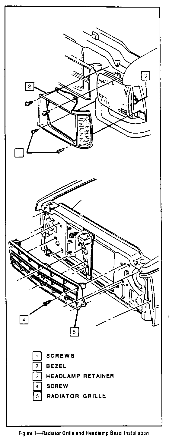
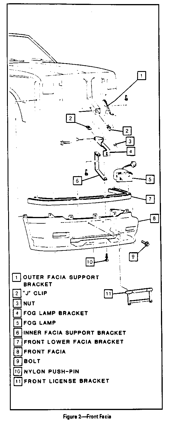
Figures 1 and 2
Remove or Disconnect
1. Open hood.
2. Head lamp bezels (2,Fig.1). Disconnect side marker lamp from bezel and hook wires around projection on headlamp retainer to keep side marker lamp and harness accessible during installation.
3. Radiator grille (5, Fig 1).
4. Using a razor knife, cut heads off nylon push-pins (10, Fig. 2) securing underside of facia to front lower facia bracket (7, Fig. 2).
5. Front lower facia bracket.
6. Bolts (9, Fig. 2) securing facia to radiator support and screws securing facia to front fender openings.
7. Front facia (8, Fig. 2).
8. Fog lamp nuts (3, Fig 2), disconnect connectors and lift off fog lamps (5, Fig. 2).
Install or Connect
Install front facia reverse of removal procedure except install fog lamps last. Use new nylon push-pins.
CAB FRONT ROCKER EXTENSION
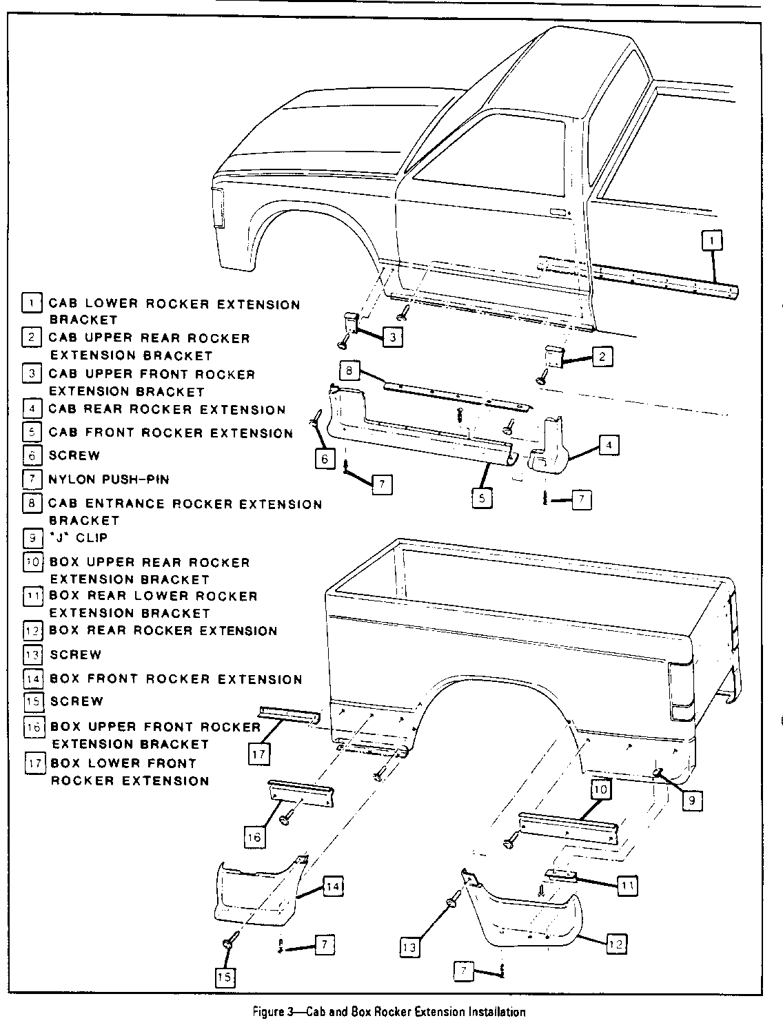
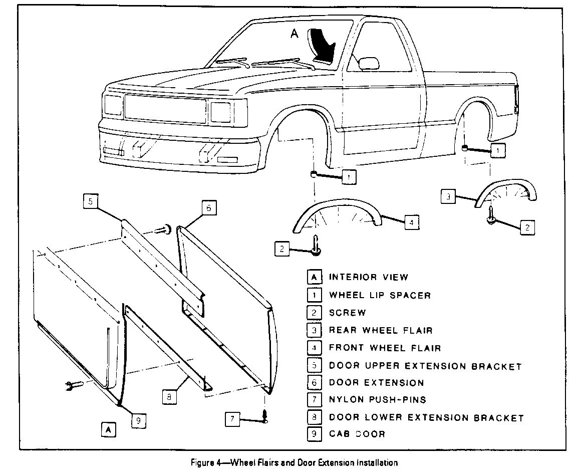
Figures 3 and 4
Remove or Disconnect
1. Loosen rear edge of front wheel flair (4, Fig. 4) sufficiently to expose screw (6, Fig. 3) securing upper edge of front rocker extension.
Important
Wheel lip spacers of varying thickness (1, Fig. 4) are used between the wheel flair and fender opening to maintain correct alignment. Mark spacers as necessary during removal to assure that spacers can be reinstalled in origi- nal positions.
2. Screw (6, Fig 3)
3. Using a razor knife, cut head off nylon push-pins securing bottom and top of front rocker extension.
4. Front rocker extension (5, Fig. 3).
Install or Connect
Install front rocker extension reverse of removal procedure and align to rear rocker extension so that approximately a 2 mm gap exists at overlap joint of parts. Use new nylon push-pins to secure.
CAB REAR ROCKER EXTENSION
Figures 3 and 5
Remove or Disconnect
1. Partially loosen cab front rocker extension (5,Fig.3) by cutting head off rearmost nylon push-pin on topside of front rocker extension, and also last three rearmost pins on underside. Use a razor knife to cut pins.
2. Work cab rear rocker extension (4,Fig.3) free from under front rocker extension and lift to remove.
Install or Connect
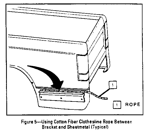
1. Using a 4' piece of cotton fiber clothesline rope, (approximately 3/8" dia. thickness), insert rope between cab upper rear rocker extension bracket (2, Fig. 3) and sheetmetal. It may be necessary to use a flat bladed plastic tool to stuff the rope in place (Fig. 5).
NOTICE: Do not use a nylon fiber rope as it may damage paint.
2. Slide upper lip of cab rear rocker extension behind bracket and pull out rope to release bracket.
3. Align rear rocker extension to front rocker extension and adjust for approximately a 2 mm gap at overap joint of parts.
4. Complete installation reverse of removal and use new push-pins to secure.
BOX FRONT ROCKER EXTENSION
Figures 3,4 and 5
Remove or Disconnect
1. Loosen front edge of rear wheel flair (3, Fig. 4) sufficiently to expose screw (15, Fig. 3) securing upper edge of front rocker extension.
Important
Wheel lip spacem of varying thickness (1, Fig. 4) are used between the wheel flair and the fender opening to maintain correct alignment. Mark spacers as necessary during removal to assure that spacers can be rein- stalled in oniginal positions.
2. Scew (15, Fig.3).
3. Using a razor knife, cut heads off nylon push-pins securing underside of rocker extension.
4. Lift and remove box front rocker extension (14,Fig. 3).
Install or Connect
1. Using a 4' piece of cotton fiber clothesline rope (approx. 3/8" dia. thickness), insert rope between box upper front rocker extension bracket (16, Fig.3) and sheetmetal. It may be necessary to use a flat bladed plastic tool to stuff the rope in place (Fig. 5).
NOTICE: Do not use nylon fiber rope as it may damage paint.
2. Slide upper lip of box front rocker extension behind bracket and pull out rope to release bracket.
3. Align as required and complete installation using new nylon push-pins to secure.
BOX REAR ROCKER EXTENSION
Figures 3, 4 and 5
Remove or Disconnect
1. Loosen rear edge of rear wheel flair (3,Fig.4) sufficiently to expose screw (13, Fig. 3) securing upper edge of rear rocker extension.
Important
Wheel lip spacers of varying thickness (1, Fig. 4) are used between the wheel flair and the fender opening to maintain correct alignment. Mark spacers as necessary during removal to assure that spacers can be rein- stalled in original positions.
2. Screw (13,Fig.3)
3. Using a razor knife, cut heads off nylon push-pins securing underside of rear rocker extension.
4. Lift and remove box rear rocker extension (12, Fig.3).
Install or Connect
1. Using a 4' piece of cotton fiber clothesline (approx.3/8" dia thickness), insert rope between box upper rear rocker extension bracket (10, Fig. 3) and sheetmetal. It may be necessary to use a flat bladed plastic tool to stuff the rope in place (Fig. 5).
NOTICE: Do not use nylon fiber rope as it may damage paint.
2. Slide upper lip of box rear rocker extension behind bracket and pll out rope to release bracket.
3. Align as required and complete installation using new nylon push-pins to secure.
DOOR EXTENSION
Figures 4 and 5
Remove or Disconnect
1. Using a razor knife, cut heads off nylon push-pins securing underside of door extension (6, Fig. 4).
2. Pull bottom edge of door extension outward and lift to remove.
Install or Connect
1. Using a 4' piece of cotton fiber clothesline rope (approx. 3/8" dia. thickness), insert rope between door upper extension bracket (5, Fig. 4) and door sheetmetal. It may be necessary to use a flat bladed plastic tool to stuff the rope in place (Fig. 5).
NOTICE: Do not use nylon fiber rope as it may damage paint.
2. Slide upper lip of door extension behind bracket and pull out rope to release bracket.
3. Align door extension as required and complete installation using new nylon push-pins to secure.
FRONT AND REAR WHEEL FLAIRS
Figure 4
Remove or Disconnect
1. Scews and wheel lip spacers (1 and 2, Fig. 4).
Important
Wheel lip spacers of varying thickness (1, Fig. 4) are used between the wheel flair and the fender opening to maintain correct alignment. Mark spacers as necessary during removal to assure that spacers can be rein- stalled in original positions.
2. Wheel flairs
Install or Connect
Install wheel flairs reverse of removal procedure.
REAR VALANCE PANEL
Figures 6 and 7
Remove or Disconnect
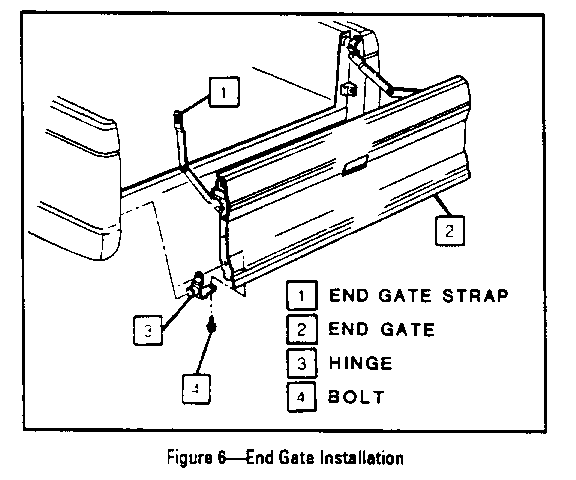
1. Release RH and LH end gate straps.
2. Two bolts securing LH (driver's side) end gate hinge (3, Fig. 6) to end gate and lift off end gate. Place on clean, protective surface.
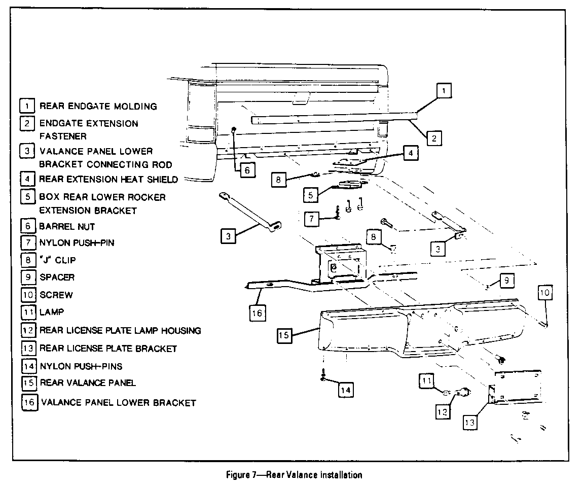
3. Using a razor knife, cut heads off nylon push-pins along bottom of valance panel (14. Fig. 7).
4. Rear license plate bracket (13, Fig. 7).
5. Rear license plate lamp housings (12, Fig. 7).
6. Screws and spacers (9 and l10, Fig.7) along top edge of valance.
7. Rear valance panel (15,Fig.7).
Install or Connect
Install valance panel reverse of removal procedure.
REAR TAILGATE MOLDING
Figure 7
Remove or Disconnect
Release chips securing tailgate molding and lift off molding.
Install or Connect
Install molding reverse of removal.
PAINT SPECIFICATIONS
Wipe parts with wax and silicone remover prior to painting.
PRIMER: PPG DEL #33434
Use material as supplied. Bake 20 minutes at 250 degrees F.
TOP COAT: Base/Clearcoat System
Inmont Codes
Red #7475 E98RM407 Black #8555 E98KK505 White #5111 E98WR507 Clear E86CA112 Catalyst E190MOO10
Add 4 percent of catalyst to raw paint, then reduce. Base and clear coats reduced to 19-22 seconds on Viscosity cup. Use PM Acetate for reducer. Bake 25 min. at 250 degrees F.
General Motors bulletins are intended for use by professional technicians, not a "do-it-yourselfer". They are written to inform those technicians of conditions that may occur on some vehicles, or to provide information that could assist in the proper service of a vehicle. Properly trained technicians have the equipment, tools, safety instructions and know-how to do a job properly and safely. If a condition is described, do not assume that the bulletin applies to your vehicle, or that your vehicle will have that condition. See a General Motors dealer servicing your brand of General Motors vehicle for information on whether your vehicle may benefit from the information.
