BRAKE ROUGHNESS/PULSATION AND DISC ROTOR SURFACE FINISHING

Subject: BRAKE ROUGHNESS/PULSATION AND DISK BRAKE ROTOR SURFACE
Model and Year: 1987-91 S1 LLV (POSTAL VEHICLE)
TO: ALL CHEVROLET DEALERS
Some of the above vehicles may experience brake roughness (pulsation) resulting from variations in rotor thickness, which generally occurs after some mileage.
Rotor thickness variation may become evident while the vehicle is in motion and the brake pedal is in the unapplied position. Three events must occur simultaneously:
1. The rotor/bearing system runout must be out of specification enough to produce high spots on the rotor face in relation to the caliper.
2. There must be a condition of caliper drag which causes the inboard and/or outboard shoe to rub on the rotor high spots.
3. The lining material must be sufficiently abrasive to cause wear on the high spots and, therefore, to develop rotor thickness variation after accumulated mileage.
Following is a discussion of each of these events along with information about the conditions which can contribute to each.
System Runout
Excessive system runout can exist as a result of the stack up of the tolerances of a rotor and a bearing which has been manufactured at one end or the other of their respective design specifications, or if either the rotor or bearing are out of specification.
The manufacturing process controls, which determine the amount of rotor or bearing runout, are continuously being improved to reduce the amount of system and/or component runout. During manufacturing of the brake rotor, tolerances of the braking surfaces for flatness, thickness variation, and lateral runout are held very close. Maintaining these close tolerances on the rotor's braking surface is necessary to prevent brake roughness.
A lateral runout check of the rotor must be performed to determine the extent of runout.
Lateral Runout Check:
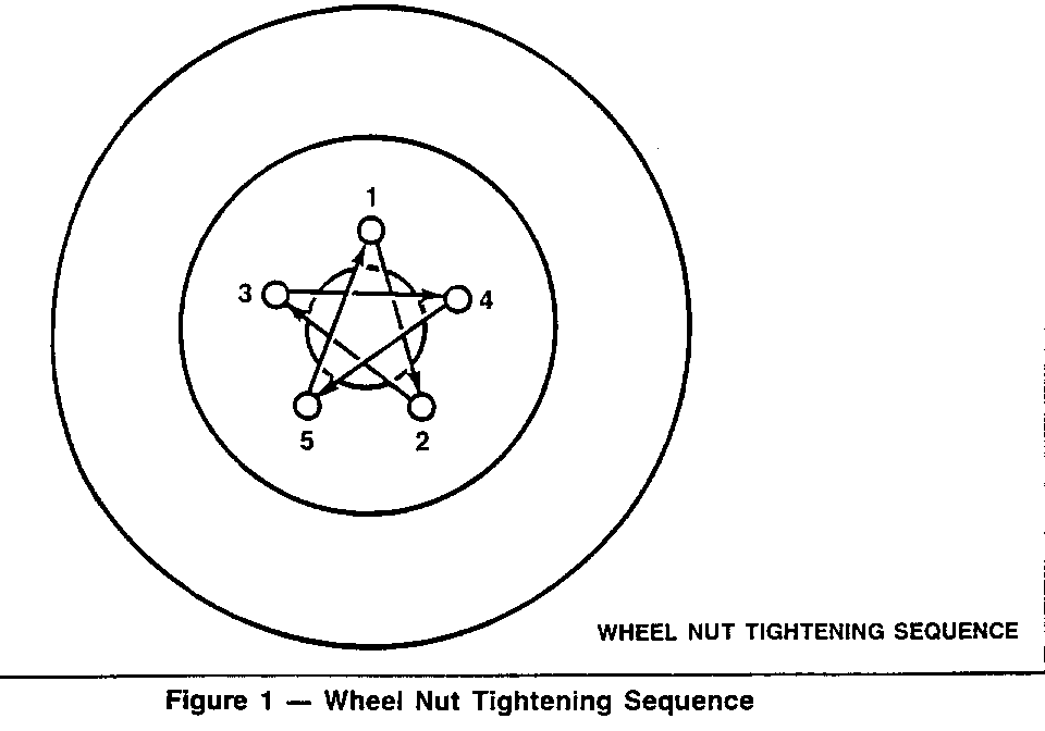
1. Remove the wheel and tire. Invert the wheel nuts and reinstall them on the studs to the specified torque. Be sure to follow the alternating nut torquing sequence to ensure proper rotor alignment.
2. Fasten a dial indicator to the caliper so the dial indicator button contacts the rotor about 13mm (0.500 inch) from the outer edge.
3. Zero the dial indicator.
4. Move the rotor one complete revolution and observe total indicated runout (TIR). Lateral runout cannot exceed 0.08mm (0.003 inch).
5. If lateral runout exceeds that specified in Step 4, refinish the rotor to specifications, reinstall rotor, and remeasure lateral runout.
Wheel Bolt Torque:
Overtorqued wheel nuts or torquing wheel nuts without following the tightening sequence can create a rotor runout condition. Refer to Figure 1.
The use of a torque wrench when tightening wheel nuts is necessary to prevent distortion of the rotor, hub, or wheel. The wheel nuts should be tightened in two steps to assure an even clamp load.
Caliper Drag:
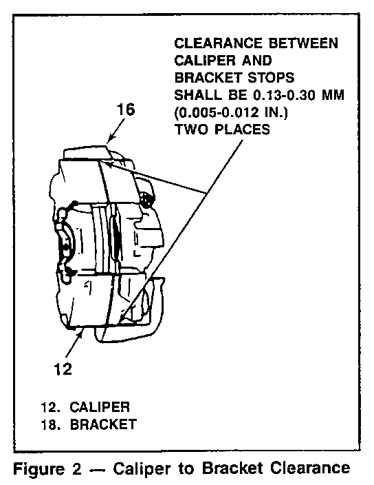
Caliper drag is usually caused by interference between the caliper to knuckle interface or a caliper bolt binding on the caliper bolt bushing.
Caliper to knuckle clearance is important. Clearance should be checked with the caliper in position and the caliper mounting bolts properly torqued. If excessive clearance exists, a clunking noise may occur on each brake apply. Too little clearance can cause caliper drag. The desired clearance is .005 - .012 in. at each caliper to knuckle bracket interface, or a total of .01 0 - .024 in. The caliper bracket stops can be filed to obtain proper clearance. Refer to Figure 2.
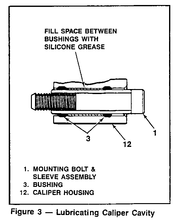
When servicing the caliper, the caliper bolts should be cleaned and the space between the caliper bolt bushings should be filled with silicone grease such as Part Number 1052863 or equivalent. This will prevent the caliper dragging or binding on the mounting bolts. Refer to Figure 3.
Lining Material Abrasiveness:
The degree of abrasiveness of the brake lining material is determined by the manufacturer. A highly abrasive material will tend to create a rotor out-of-parallel condition if system runout and caliper drag are present.
The properties and characteristics of brake linings are specified by Product Engineering. Some brake lining designs may be more aggressive when stopping, i.e. higher friction coefficient, while others are less aggressive but may be very durable and long lasting. The linings for any specific vehicle are selected on the basis of friction, wear, etc., to optimize front and rear braking for that specific vehicle.
The brake lining used should be service kit SPO # 12321426 OR AC DELCO Catalog 171-0299.
Brake pedal pulsation can also occur in the rear on drum brakes if there is radial runout in the drum and/or axle flange, or bearing.
Thickness Variation Check:
If a brake pedal pulsation condition is felt, a thickness variation check should be performed on the rotor.
Thickness variation can be checked by measuring the thickness of the rotor at four or more points around the circumference of the rotor. Use a micrometer calibrated at one tenth increments per .001 inch. All measurements must be made at the same distance in from the edge of the rotor.
A rotor that varies by more than 0.013 mm (0.0005 inch) can cause pedal pulsation and/ or front end vibration during brake applications. A rotor that does not meet these specifications should be refinished or replaced as necessary.
Rotor Refinish Recommendations:
Rotor refinish should only be performed because of brake roughness (pulsation). When replacing a rotor with a new rotor from stock it should NOT require refinishing unless one of the conditions mentioned above is present. Also, routine replacement of disc brake linings does NOT require rotor refinishing.
When rotor refinishing is required, the following recommended procedures should be used to obtain the proper micro-inch surface finish which is required for new rotor (10 to 50 micro-inches with nondirectional swirl pattern). When refinishing a rotor for a roughness (pulsation), it is recommended that at least 0.010 inch be removed from the inboard and outboard side of the rotor surface to ensure removal of the high and low spots on the face of the rotor.
Rough Cut Finish Cut --------- ---------- Spindle 150 rpm 150 rpm Depth of Cut Per Side .005 inch .002 inch Tool Cross Feed Per Rev. 0.006 - .010 inch .002 inch max. Vibration Dampener Yes Yes Swirl Pattern-120 GRIT No Yes
The following is also important:
- The brake lathe must be in good working order and have capability to produce the intended surface finish.
- Excessive spindle speed or too deep a cut can result in a rough finish.
- Cutting tools must be sharp.
- The rotor surface contacting the arbor and/or the adapter must be free of debris and coarse surface corrosion.
- If the dealership's rotor turning equipment cannot produce a finish cut equivalent to a new rotor's surface, finish cuts may be further improved and made nondirectional by dressing the rotor surface with a sanding disc power tool.
Light scoring of the rotor surfaces, which may result from normal use, will not affect brake operation.
To become familiar with the required surface finish, drag a fingernail over the surface of a new rotor from the parts stock or one on a new vehicle. If your brake equipment cannot produce this smooth a finish when correctly used, contact the equipment manufacturer for corrective instructions.
Following these refinishing specifications and recommendations will help to hold the rotor surface finish to the specified range. Controlling the braking surface finish of the rotor is necessary to provide adequate early stopping ability and to avoid pulls and erratic performance and will aid in extending lining life.


General Motors bulletins are intended for use by professional technicians, not a "do-it-yourselfer". They are written to inform those technicians of conditions that may occur on some vehicles, or to provide information that could assist in the proper service of a vehicle. Properly trained technicians have the equipment, tools, safety instructions and know-how to do a job properly and safely. If a condition is described, do not assume that the bulletin applies to your vehicle, or that your vehicle will have that condition. See a General Motors dealer servicing your brand of General Motors vehicle for information on whether your vehicle may benefit from the information.
