DRIVELINE MOAN, DROAN OR VIB. AT 2800 RPM-INTERIOR VIBRATES

SUBJECT: DRIVELINE MOAN DROAN RESONANCE VIBRATION AT 2800 RPM - INSTALL DAMPER KIT
VEHICLES AFFECTED: 84-86, 89-91 'S' PICKUP W/BORG-WARNER M/T AND 2.5L
Some 1984-86 and 1989-91 S pickup trucks may experience a condition described as driveline moan, drone, resonance or vibration. This condition usually occurs at approximately 2800 rpm when the cab and/or interior panels may buzz or vibrate.
Service damper kits are available for installation on these S pickup trucks. These dampers will significantly reduce vibrations in the 2800 rpm range. Refer to the SERVICE PROCEDURE section for the specific action required for the model years listed.
VEHICLES INVOLVED
1984-1986 and 1989-1991 S pickup trucks (models S10603, S10653, S10803) equipped with 2.5L engine and Borg-Warner 4 or 5 speed manual transmission.
SERVICE PROCEDURE
1984 - 1986 S pickup trucks:
These vehicles can be repaired using the damper P/N 14073312 and method described in Product Service Bulletin 83-7-127 This bulletin calls for a transmission mount change on some models. If the transmission mount features the dual captive stud mounting, the transmission mount does not require replacement.
1989 - 1991 S pickup trucks:
Service damper kit P/N 15674891 containing a damper, new transmission extension housing with damper mounting bosses and fasteners should be installed.
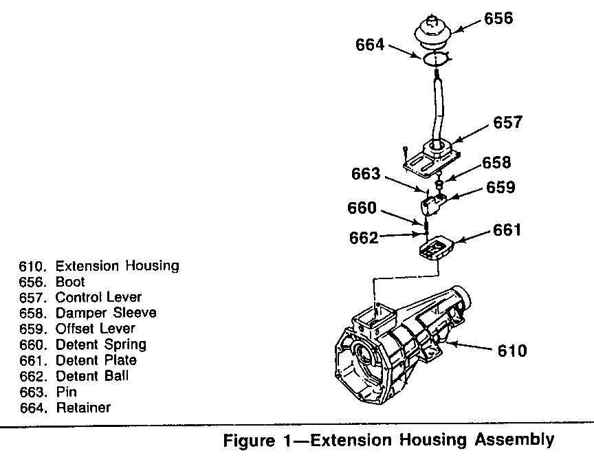
REMOVE-(Figure 1)
1. Transmission from vehicle.
- Refer to Section 7B of the appropriate S/T Service Manual for complete transmission removal procedure.
- Drain transmission before removal.
IMPORTANT: Do not let the transmission hang from the clutch.
2. Speed sensor from extension housing.
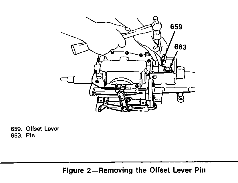
3. Roll pin (663) from offset lever.
- Place offset lever (659) in 3-4 position of neutral.
- Use a pin punch and hammer to drive the roll pin (663) through the shift shaft as shown in Figure 2.
IMPORTANT: Removal of the shift roll pin from the offset lever must be done with the offset lever in the 3-4 position of neutral or the pin may be driven into the detent/guide plate, damaging the plate and preventing further disassembly of the transmission.
4. Extension housing (610) from transmission.
- Remove the eight bolts holding the extension housing to the case.
- Separate the extension housing from the transmission case and slide rearward. The offset lever (659) will also separate from the shift shaft.
IMPORTANT: The offset lever is engaged into the extension housing and cannot be removed when the extension housing is mounted to the transmission.
- Detent ball (662) and detent spring (660) from the detent/guide plate.
- Clean old sealer from extension housing mating surface.
5. Roll pin (663) from the offset lever (659).
IMPORTANT: Failure to remove the roll pin from the offset lever may result in driving the pin into the detent/guide plate during assembly making future disassembly difficult.
INSTALL (Figure 1)
1. New extension housing (610).
- Apply a 3mm (1/8-inch) diameter bead of RTV sealant on the sealing surface of the extension housing.
- Lubricate the detent/guide plate with lithium grease and install the detent ball (662) in the 3-4 neutral position of the detent plate.
- Place the offset lever (659) and detent spring (660) over the detent ball (662) .
- Slide the extension housing against the transmission case while guiding the offset lever (659) over the shift shaft.
2. Extension to case bolts.
- Apply sealer to threads of top 2 bolts.
- Tighten bolts to 30 N.m (25 lbs. ft.).
3. Offset lever roll pin (663).
4. Speed sensor.
5. Transmission.
- Refer to Section 7B of the appropriate S/T Service Manual for complete transmission installation procedure.
- Refill transmission with fluid.
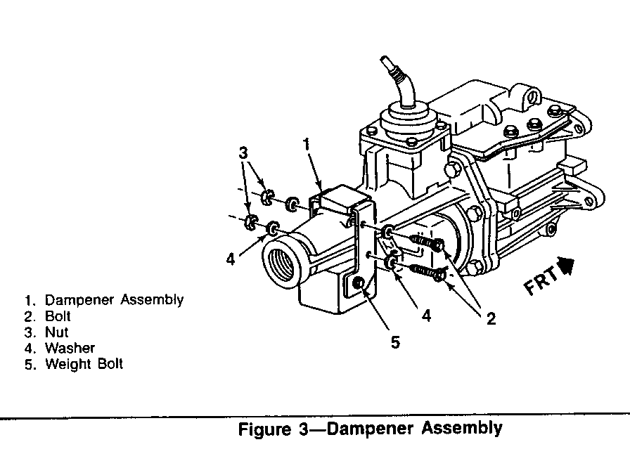
6. Damper to transmission as shown in Figure 3.
-Be sure damper is installed facing in the proper direction.
-Tighten bolts (2) to 45 N.m (35 ft.lbs.).
-Tighten weight bolt (5) to 100 N.m (75 ft.lbs.).
SERVICE PARTS INFORMATION
Part Number Description ----------- ------------------------------- 15674891 Damper Kit, Driveline Vibration
WARRANTY INFORMATION
For vehicle repaired under warranty use:
Labour Operation: T7156 Labour Time: 2.6 hrs
NOTE: Labour Operation is coded to base vehicle coverage in the warranty system.


General Motors bulletins are intended for use by professional technicians, not a "do-it-yourselfer". They are written to inform those technicians of conditions that may occur on some vehicles, or to provide information that could assist in the proper service of a vehicle. Properly trained technicians have the equipment, tools, safety instructions and know-how to do a job properly and safely. If a condition is described, do not assume that the bulletin applies to your vehicle, or that your vehicle will have that condition. See a General Motors dealer servicing your brand of General Motors vehicle for information on whether your vehicle may benefit from the information.
