Removal Procedure
- Relieve the fuel system pressure. Refer to Fuel Pressure Relief .
- Disconnect the negative battery cable. Refer to
Caution: Unless directed otherwise, the ignition and start switch must be in the OFF or LOCK position, and all electrical loads must be OFF before servicing any electrical component. Disconnect the negative battery cable to prevent an electrical spark should a tool or equipment come in contact with an exposed electrical terminal. Failure to follow these precautions may result in personal injury and/or damage to the vehicle or its components.
in General Information. - Remove vacuum hose from regulator.
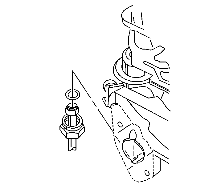
- Remove the fuel return pipe clamp.
- Remove the fuel return pipe and the O-ring from the regulator.
- Discard the O-ring.
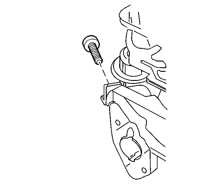
- Remove the pressure regulator bracket attaching screw.
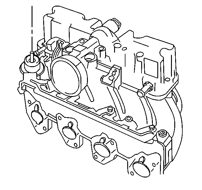
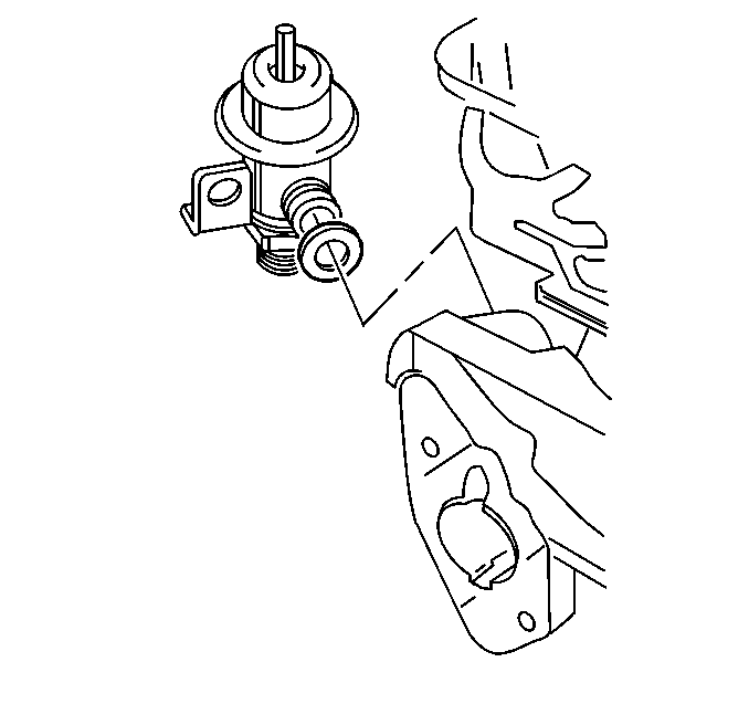
- Remove the pressure regulator assembly.
- Remove the O-ring.
- Discard the O-ring.
- If reinstalling the fuel pressure regulator, inspect the filter screen if equipped for contamination.
- If contaminated, replace the filter screen
Caution: Remove the fuel tank cap and relieve the fuel system pressure before servicing the fuel system in order to reduce the risk of personal injury. After you relieve the fuel system pressure, a small amount of fuel may be released when servicing the fuel lines, the fuel injection pump, or the connections. In order to reduce the risk of personal injury, cover the fuel system components with a shop towel before disconnection. This will catch any fuel that may leak out. Place the towel in an approved container when the disconnection is complete.


Thread-locking Compound
Notice: Do not use a higher strength locking compound than recommended when precoating the screws. Doing so could make removing the screw extremely difficult or result in damaging the screw head.
The service repair kits are supplied with a small vial of thread-locking compound with directions for use. If the material is not available, use Loctite 262 or the equivalent.
Notice: Do not immerse the TP sensor and IAC valve in any type of cleaner. This cleaning method may damage these electronic components.
Do not use a cleaner that contains methyl ethyl ketone, an extremely strong solvent, and not necessary for this type of deposit.
The throttle body metal parts may be cleaned following the disassembly in a cold immersion-type cleaner such as GM X-55 or the equivalent.
Installation Procedure
- After lubricating the new pressure regulator O-ring with clean engine oil, install on the pressure regulator.
- Install the pressure regulator assembly onto the manifold.
- Install the pressure regulator bracket attaching screw coated with the appropriate thread-locking material. Refer to Thread Locking Material below.
- Install the vacuum hose to the regulator.
- After lubricating the new fuel return pipe O-ring with clean engine oil, install on the end of pipe.
- Install the fuel return pipe to pressure regulator
- Install the fuel return pipe clamp attaching nut to the lower manifold assembly.
- Tighten the fuel filler cap.
- Connect the negative battery terminal.
- Turn ignition switch to the ON position for 2 seconds.
- Turn the ignition switch to the OFF position for 10 seconds.
- Turn the ignition switch to the ON position.
- Check for fuel leaks.


Tighten
Tighten the pressure regulator bracket attaching screw to 3.5 N·m
(31 lb. in.).
Notice: Use the correct fastener in the correct location. Replacement fasteners must be the correct part number for that application. Fasteners requiring replacement or fasteners requiring the use of thread locking compound or sealant are identified in the service procedure. Do not use paints, lubricants, or corrosion inhibitors on fasteners or fastener joint surfaces unless specified. These coatings affect fastener torque and joint clamping force and may damage the fastener. Use the correct tightening sequence and specifications when installing fasteners in order to avoid damage to parts and systems.


Tighten
Tighten the fuel return pipe attaching nut to 3.0 N·m (22 lb.
in).
