Removal Procedure
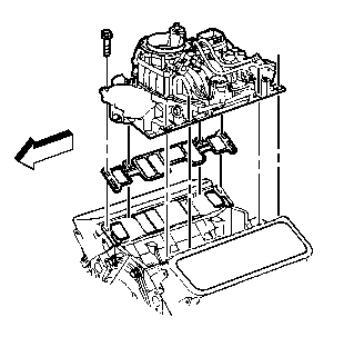
- Remove the intake manifold. Refer to Intake Manifold Replacement (Lower)
.
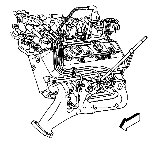
- Remove the exhaust manifold. Refer to Exhaust Manifold Replacement
.
- Remove the following components from the left cylinder head.
| • | The electrical connector at the coolant temperature sensor |
| • | The air conditioning compressor and bracket. Refer to Heating,
Ventilation and Air Conditioning. |
- Remove the generator and bracket from the right cylinder head.
Refer to Engine Electrical.
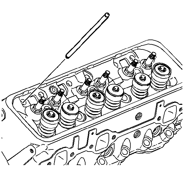
- Remove the pushrods. Refer to Valve Rocker Arm and Push Rod Replacement
.
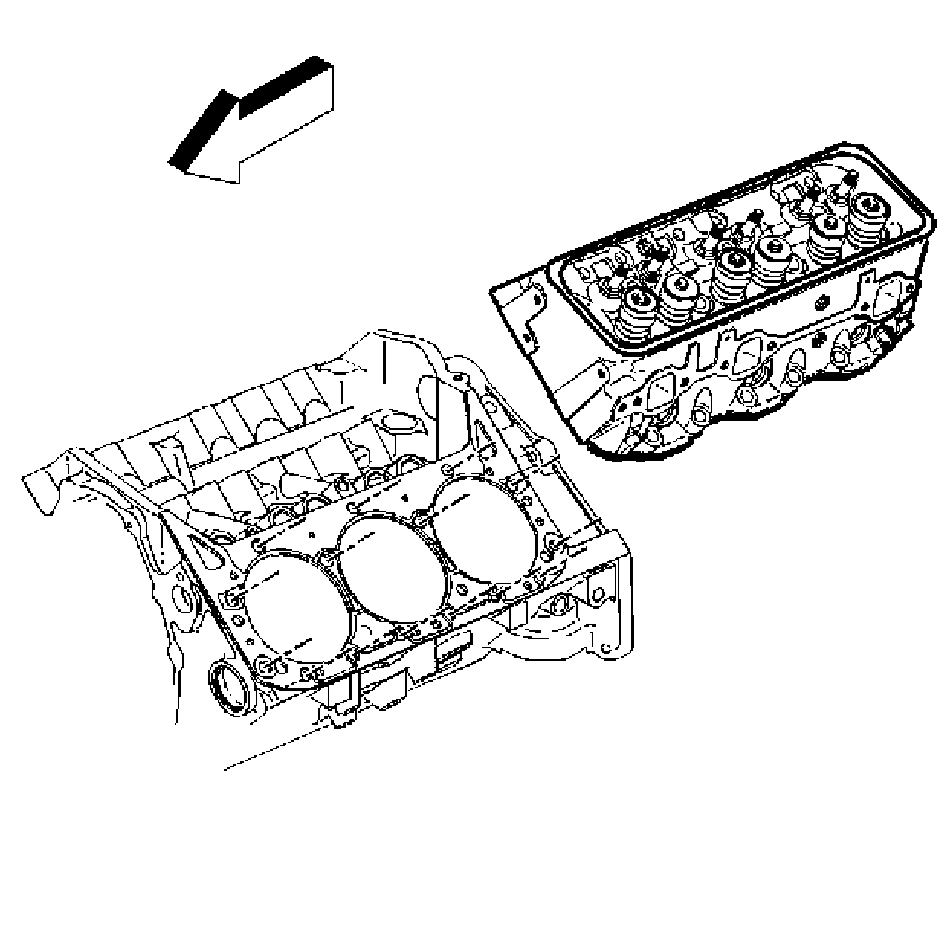
- Remove the cylinder head. Refer to Cylinder Head Removal
.
Installation Procedure
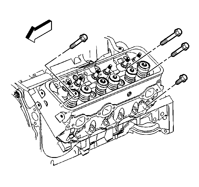
- Install the cylinder head. Refer to Cylinder Head Installation
.

- Install the pushrods. Refer to Valve Rocker Arm and Push Rod Replacement
.
- Install the following components to the left cylinder head:
| 3.1. | The electrical connector at the coolant temperature sensor |
| 3.2. | The air conditioning compressor and bracket. Refer to Heating,
Ventilation and Air Conditioning. |
- Install the generator and bracket to the right cylinder head.
Refer to Engine Electrical.

- Install the exhaust manifold. Refer to Exhaust Manifold Replacement
.

- Install the intake manifold. Refer to Intake Manifold Replacement (Lower)
.


