Restraint Devices

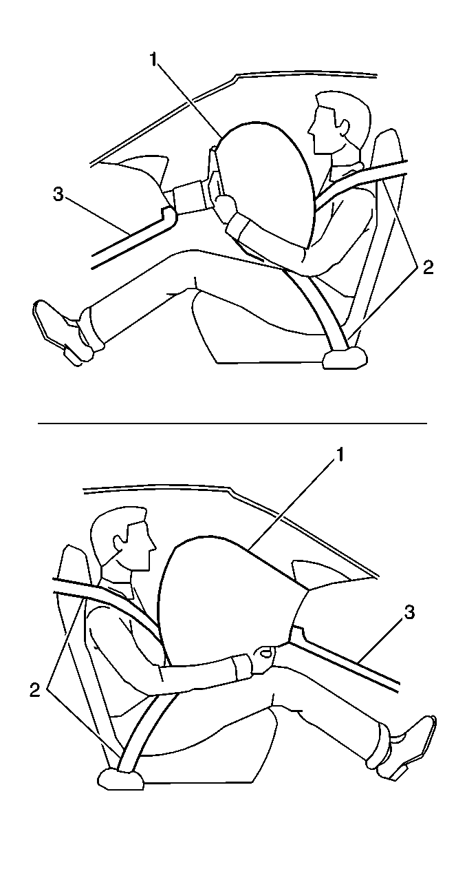
The supplemental inflatable restraint (SIR) system supplements the protection offered by the driver and front passenger seat belts (2). The SIR system deploys an air bag (1) from the center of the steering wheel and from the right side of the instrument panel.
The knee bolsters (3) and the steering column absorb crash energy. The driver and passenger knee bolsters are below the instrument panel.

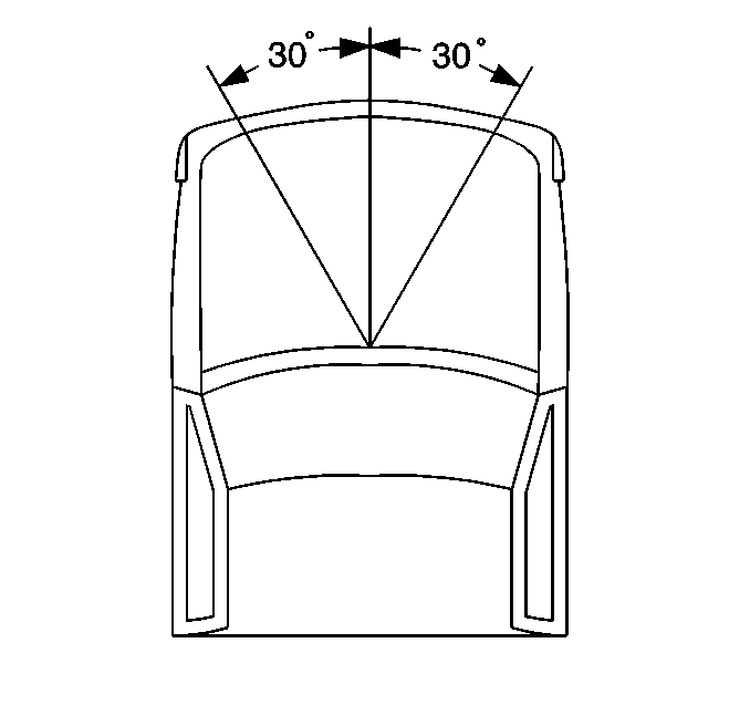
A frontal crash of sufficient force up to 30 degrees off the centerline of the vehicle will deploy the air bags.
System Description
The SIR system consists of the following components:
| • | Inflatable restraint sensing and diagnostic module (SDM) |
| • | Inflatable restraint steering wheel module |
| • | Inflatable restraint steering wheel module coil |
| • | Inflatable restraint IP module |
| • | Inflatable restraint IP module switch |
| • | Inflatable restraint front end discriminating sensor |
| • | AIR BAG warning lamp in the instrument cluster |
The function of the deployment loops is to supply current through the inflator modules, which will cause deployment of the air bags. Deployment occurs when the SDM detects vehicle velocity changes severe enough to warrant deployment.
The SDM contains a sensing device (accelerometer) that converts vehicle velocity changes to an electrical signal. The SDM compares this electrical signal to a value stored in memory. When the generated signal exceeds the stored value, the SDM performs additional signal processing and compares the generated signals to values stored in memory. When two of the generated signals exceed the stored values, the SDM will cause current to flow through the inflator modules, deploying the air bags.
An auxiliary inflatable restraint front end discriminating sensor assists the SDM in determining when a deployment should occur by providing an input signal to the SDM.
The IP module switch is directly interfaced to the inflatable restraint sensing and diagnostic module (SDM). The SDM senses the state of the IP module switch. When the switch is in the ON position, the SDM enables possible deployment of the inflatable restraint IP module. When the switch is in the OFF position, the SDM disables or inhibits possible deployment of the inflatable restraint IP module.
