INSUFFICIENT COOLING-HIGH TEMP (NEW PART NUMBER RELEASED)

SUBJECT: INSUFFICIENT COOLING IN HIGH AMBIENT TEMP. (INSTALL WATER VALVE/INSULATOR COVER AND UNDERBODY SHIELD)
VEHICLES AFFECTED: 1988-1991 S/T WITH A/C ------------------------------------------------------------------------------
THIS BULLETIN IS BEING REVISED TO PROVIDE ADDITIONAL INFORMATION ON INSTALLATION OF AN UNDERBODY SHIELD AND TO INCLUDE THE 91 S/T MODELS.
Some owners of 1988-1991 S/T model vehicles with air conditioning may comment about insufficient cooling in high ambient temperatures. To address this condition two service modifications have been developed.
1. Installation of coolant shut off valve which actuates in A/C Max mode and an insulated cover for the accumulator.
2. Installation of an under body shield (P/N 15564769) to improve cooling and direct air flow through the condenser (T-TRUCK ONLY).
SERVICE PROCEDURES:
Water Valve Installation:
CAUTION:
Coolant may be pressurized and hot. Use care to ensure that the coolant is at ambient temperature. Possible burns could result from contact with hot coolant.
1. Drain the coolant.
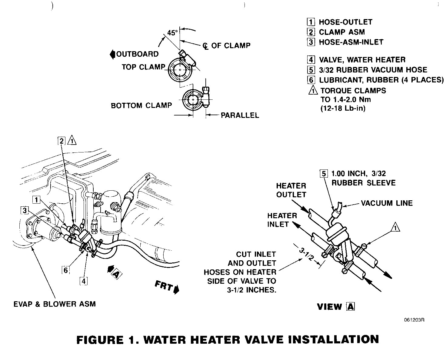
2. Cut the heater inlet and outlet hoses approximately 88.9 mm (3.5 in) from the cowl Refer to Figure 1.
- It may be necessary to cut about one inch out of each hose to allow the water heater valve (4) to be inserted. The exact amount of hose will depend on hose routing for different engine configurations.
3. Insert the heater water valve (P/N 14044414)(Figure 1, "4") in the hoses and install the hose clamps (P/N 12337891)(Figure 1, "2"). Torque the clamps to 1.4 - 2.0 N.m. (12 - 18 in. lbs.)
IMPORTANT: If the wiring for the blower relay shows evidence of interference with the valve, add convoluted conduit to protect the wires and tie strap the wires as necessary to avoid rubbing.
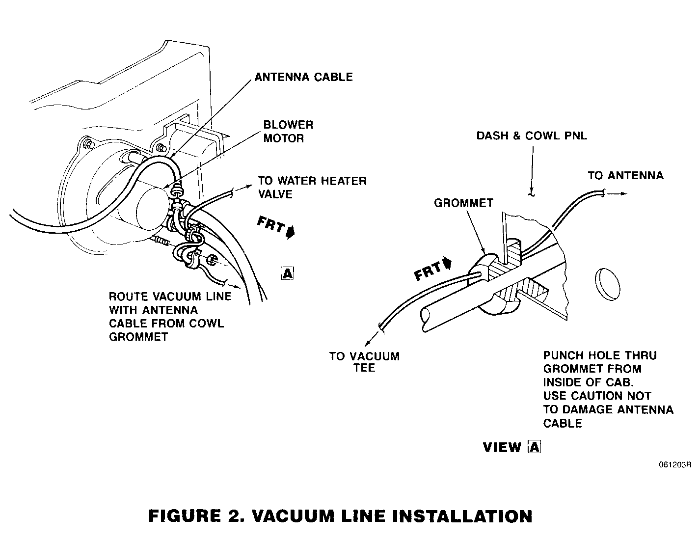
4. Install plastic vacuum line on the water valve fitting and add a 2.4 mm (3/32 in.) rubber sleeve for coupling (Figure 1). Route vacuum line with the antenna cable to the grommet into the dash area Refer to Figure 2.
5. Punch a hole in the grommet with a pick, being careful not to puncture the antenna cable.
6. Route the vacuum line under the dash to the glove box area Refer to Figure 3.
7. Open the glove box and remove the rear panel to gain access to the rear of the dash. It will also be necessary to remove the insulator assembly under the dash for full access. Locate the Max A/C line going to the plenum valve and the air recirculation door valve. The line is black plastic with an orange stripe.
8. Cut the line and insert Tee coupling (P/N 6272766)(Figure 3, View A). Use 2.4 mm (3/32 in.) rubber vacuum line for the couplings. Install the added vacuum line to the bottom leg of the Tee.
9. Reinstall under dash insulator and the rear panel of the glove box door.
Accumulator Insulation Installation:
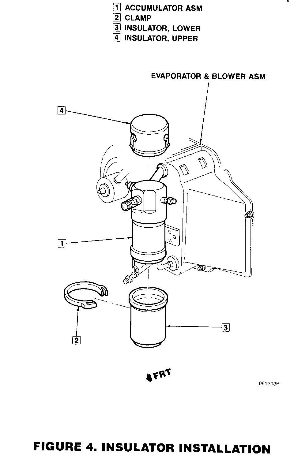
1. Install the upper and lower insulators (P/N 15612121 and 15612120) (Figure 4, "3" and "4") on the A/C accumulator assembly.
IMPORTANT: The insulator is designed for a G-van and must be modified for use on an S/T truck accumulator.
2. Cut the lower insulator as necessary to fit the accumulator mounting bracket. Cut the upper insulator as necessary to accommodate the A/C pipes and fittings.
3. Install the clamp (P/N 15530486) (Figure 4, "2") on the insulators at the overlapped portion and tighten the clamp.
Inspection:
----------- 1. Start the engine and check all hose connections for leaks.
2. Place the climate control lever in the "Max A/C" position and ensure that the water valve is operating properly.
Underbody Shield Installation (T-TRUCK W/0 ZM5 UNDERBODY SHIELD OPT.)
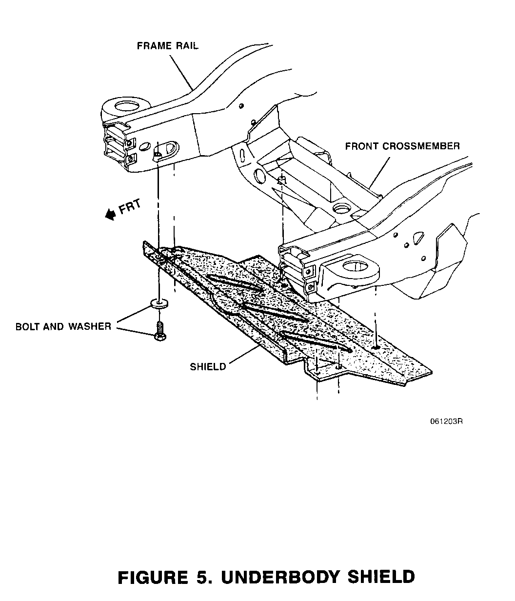
NOTE: Installation of this shield will improve engine cooling and assist in directing air flow through the condenser and radiator.
1. Raise vehicle on a hoist to access the underbody.
2. Place the shield (P/N 15564769) so that the back edge rests on the front crossmember and the front outer edges rest on the frame rails Refer to Figure 5.
3. Align the shield attachment holes with the pre-drilled threaded holes on the front crossmember and frame rails.
4. Torque the six (6) attachment bolts (P/N 11509171) and washers (P/N 15596486) to 38 N.m. (8.5 ft.lbs.)
5. Lower the vehicle on the hoist.
SERVICE PARTS INFORMATION
Part Number Description Quantity ----------- ----------- -------- 14044414 Valve, heater water 1
15612120 Insulator, accumulator lower 1
15612121 Insulator, accumulator upper 1
15530486 Clamp, insulator 1
12337891 Clamp, water hose 8
6272766 Tee, vacuum hose 1
* Hose, 3/4 inch heater water as req'd
* Hose, 5/8 inch heater water as req'd
* Hose, vacuum, plastic as req'd
* Hose, vacuum, 3/32 inch rubber as req'd
15564769 Shield 1
11509171 Bolt 6
15596486 Washers 6
* Part may be obtained locally at most hardware stores
Parts are currently available from CANSPO.
WARRANTY INFORMATION
For vehicles repaired under warranty use:
Description Labour Time ----------- ------------ Valve and insulator installation. 0.7 hrs.
Underbody shield installation. 0.3 hrs.

General Motors bulletins are intended for use by professional technicians, not a "do-it-yourselfer". They are written to inform those technicians of conditions that may occur on some vehicles, or to provide information that could assist in the proper service of a vehicle. Properly trained technicians have the equipment, tools, safety instructions and know-how to do a job properly and safely. If a condition is described, do not assume that the bulletin applies to your vehicle, or that your vehicle will have that condition. See a General Motors dealer servicing your brand of General Motors vehicle for information on whether your vehicle may benefit from the information.
