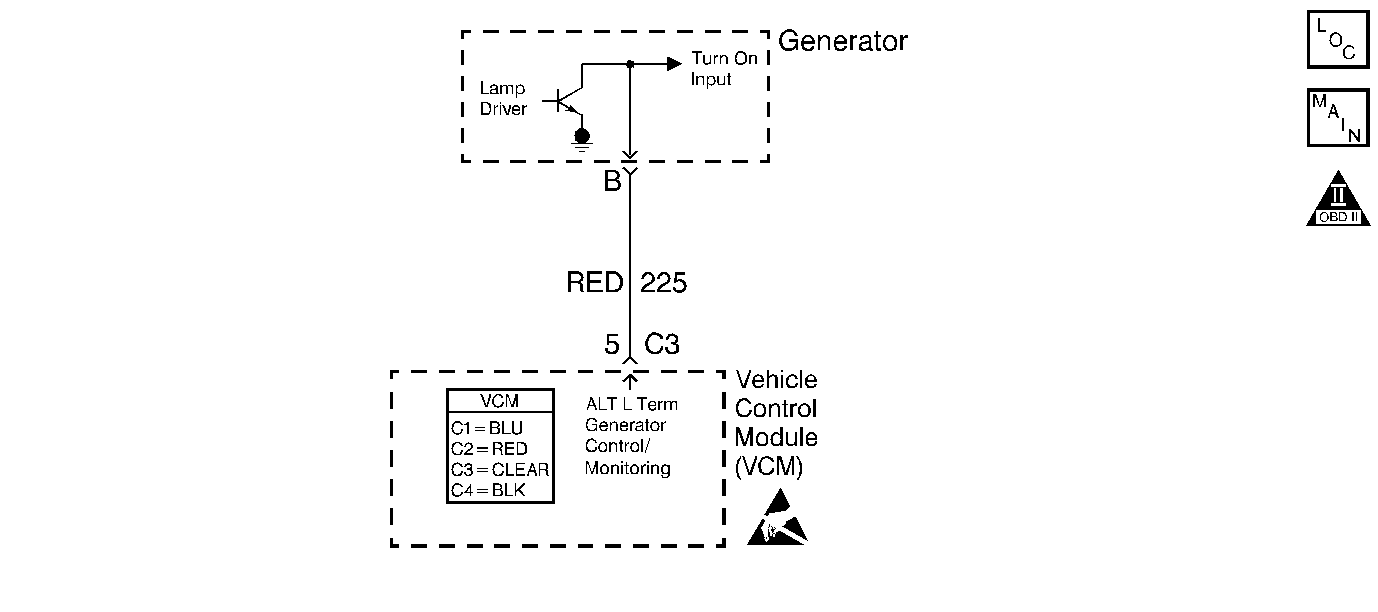
Circuit Description
The VCM Controlled Generator Diagnostic is designed to diagnose the generator lamp terminal. The VCM provides a voltage signal to the generator L-terminal. The generator will charge the battery whenever it receives the VCM input. The generator voltage regulator will pull the terminal input low when the engine is not running or the generator is not working properly. Any interruption in the VCM input will cause the generator to stop charging.
Diagnostic Aids
The VCM communicates to the IP through the Class 2 serial data line. Check for any Class 2 DTCs that would indicate a loss of communication between the VCM and the IP.
An intermittent may be caused by a poor connection, rubbed through wire insulation, or a broken wire inside the insulation.
Thoroughly check any circuitry that is suspected of causing the intermittent complaint for the following conditions:
| • | Backed out terminals |
| • | Improper mating |
| • | Broken locks |
| • | Improperly formed or damaged terminals |
| • | Poor terminal to wire connections |
| • | Physical damage to the wiring harness |
| • | Corrosion |
| • | Moisture in the connector |
Test Description
-
If the IP voltmeter does not read near the voltage reading displayed on the DMM at the generator output terminal, the IP gauge or related IP wiring could be the problem.
-
If the generator L terminal pin is probed at the generator with a test lamp to B+ the generator should charge the battery. Replace the generator if it is not charging.
Step | Action | Value(s) | Yes | No |
|---|---|---|---|---|
1 | Was the On-Board Diagnostic (OBD) System Check performed? | -- | ||
2 |
Did the light turn OFF? | -- | ||
3 | Check for a short to ground in the Generator Control/Monitoring circuit. Did you find a problem? | -- | ||
4 | Measure the voltage at the generator output terminal on the generator with a J 39200 DMM. Did the meter indicate a voltage above the specified value? | 12.6 V | ||
View the IP voltmeter. Did the voltmeter indicate a value above the specified value? | 12.6 V | Go to Diagnostic Aids | Go to Instrument Panel Cluster (IPC) System Check | |
Did the meter indicate a voltage above the specified value? | 12.6 V | |||
7 | Check for an open or short to ground in the Generator Control/Monitoring circuit. Did you find a problem? | -- | ||
8 | Repair the circuit as necessary. Refer to Wiring Repairs . Is the action complete? | -- | -- | |
9 | Replace the generator. Refer to Generator Replacement 4.3L. Is the action Complete? | -- | -- | |
10 |
Is the action complete? | -- | -- | |
11 | Operate the vehicle within the conditions under which the original symptom was noted. Does the system now operate properly? | -- | System OK |
