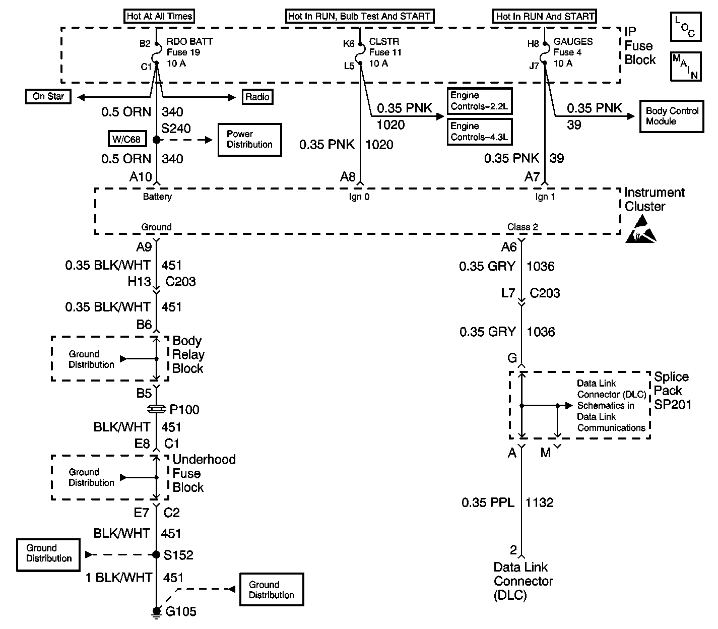
Circuit Description
The IPC monitors the Class 2 messages and compares them to the inputs from the various sensors and gauges. The instrument panel cluster also monitors the ignition switch position based on the ignition signal inputs. The instrument panel cluster has a built in microprocessor. The microprocessor performs a self test on power up.
Conditions for Clearing the MIL/DTC
| • | A history diagnostic trouble code (DTC) will clear after 100 consecutive ignition cycles without a fault present. |
| • | Use a scan tool in order to clear the history and current DTC(s). |
Diagnostic Aids
| • | Verify that the following fuses are OK: |
| - | RADIO BATT |
| - | CLUSTER |
| - | ILLUMINATION |
| - | GAUGES |
| • | The IPC performs a self-check on power up. Turn the ignition switch to the RUN position and observe the conditions listed in the Cluster Power-up Function Check Table. |
| • | A scan tool reads Class 2 messages with the ignition switch in the RUN position. |
| • | Use a scan tool in order to test for DTCs. |
Test Description
The number(s) below refer to the step number(s) on the diagnostic table.
-
This step inspects the IPC's circuits for power and ground.
-
This step inpects the integrity of the Class 2 bus and all of the associated modules.
-
This is the IPC self test.
-
This step checks the operation of the PRNDL.
Step | Action | Value(s) | Yes | No | ||||||||||||||||||||||||
|---|---|---|---|---|---|---|---|---|---|---|---|---|---|---|---|---|---|---|---|---|---|---|---|---|---|---|---|---|
1 | Inspect all IPC power and grounds. Are the power and grounds OK? | -- | Go to Step 2 | Go to Testing for Intermittent Conditions and Poor Connections in Wiring Systems | ||||||||||||||||||||||||
2 |
Are any of the modules on the Class 2 serial data link not communicating? | -- | Go to Step 3 | Go to Data Link Communications System Check in Wiring Systems | ||||||||||||||||||||||||
3 |
Important: Do not start the engine or move the automatic transmission shifter from the PARK position.
Are the power-up indications correct? | -- | Go to Step 4 | Go to Applicable Diagnostic Table | ||||||||||||||||||||||||
4 |
Does the indicator correspond to the shift lever positions? | -- | Go to Step 5 | Go to Functional Test in Automatic Transmission | ||||||||||||||||||||||||
5 | Inspect for DTCs with the scan tool. Are any DTCs present? | -- | Go to Applicable Diagnostic Table | System OK |
