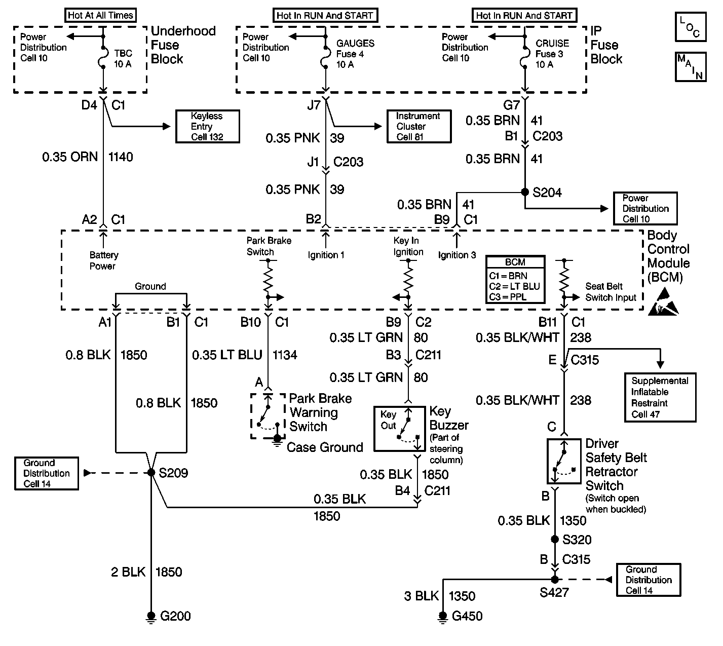
Circuit Description
Important:
• After performing a repair that requires clearing DTC(s) from the
BCM, inspect the repair by operating the vehicle within the limits shown in
Conditions for Setting the DTC. Operating the vehicle under these specifications
will verify that the repair was completed properly. • Use the J 35616
when
probing electrical circuits in order to prevent damage to damage to electrical
components and connectors. The J 35616
is the ONLY recommended method of probing connectors, terminals, and bussed
electrical centers (BECs). The J 35616
contains an assortment of flexible connectors used in order to preobe connectors,
terminals and BECs during diagnosis. • Do not use a test lamp in order to diagnose the BCM electrical
systems unless you are specifically instructed by diagnostic procedures. Use
the J 35616
when diagnostic procedures
require probing of connectors. Refer to
Special Tools
. • The body control module (BCM) will withstand normal current draws
associated with the vehicle operations. Do not overload any circuit. • When you test for opens or shorts, do not ground or apply voltage
to the BCM circuits unless instructed to do so. Use a J 39200
digital multimeter (DMM) (or equivalent) in
order to test these circuits. Test electrical circuits using a DMM while the
BCM connectors remain connected to the BCM or to the recommended breakout
box. • Do not remove or apply the voltage to the BCM when the key is
in the RUN position. Always turn the key to the LOCK position when any of
the following components are removed or connected: - Battery cables - Fuses - Connectors • Whenever a BCM removal or replacement procedure is performed,
follow the instructions in this section. Use the following guidelines when
servicing the BCM system: - Always DISCONNECT the BCM connector (BRN) FIRST. - Always CONNECT the BCM connector (BRN) LAST. • The BCM may set codes when the ignition switch is in the OFF position.
When you disconnect the electrical connectors from the BCM, the DTCs will
set. The BCM may require 20 minutes (1216 seconds) in order
to power down after the following conditions exist: - The ignition switch is turned to the OFF position. - The BCM is not receiving any active inputs. - The BCM does not receive any active inputs for 20 minutes.
The body control module (BCM) diagnostic system check is a test that identifies a malfunction in the electronic system. The BCM diagnostic system check is the starting point for any BCM complaint. Understand and use the BCM diagnostic system check table in order to reduce diagnostic time and prevent unneeded replacement of components.
Step | Action | Value(s) | Yes | No |
|---|---|---|---|---|
1 | Connect the scan tool. Does the scan tool turn ON? | -- | Go to Step 2 | Go to Scan Tool Inoperative in Wiring Systems |
2 | Using the scan tool, attempt to establish communications with the BCM. Does the scan tool communicate with the BCM? | -- | System OK | Go to Step 3 |
3 | Inspect the TBC fuse in the UBEC. Is the TBC fuse open? | -- | Go to Step 4 | Go to Step 5 |
4 |
Is the repair complete? | -- | Go to Step 2 | -- |
5 | Inspect the GAUGES fuse in the IP fuse block. Is the GAUGES fuse open? | -- | Go to Step 6 | Go to Step 7 |
6 |
Is the repair complete? | -- | Go to Step 2 | -- |
7 | Measure the voltage at the TBC fuse. Is battery voltage available at the TBC fuse? | -- | Go to Step 9 | Go to Step 8 |
8 | Repair the power supply circuit for the TBC fuse. Is the repair complete? | -- | Go to Step 2 | -- |
9 |
Is battery voltage available at the GAUGES fuse? | -- | Go to Step 11 | Go to Step 10 |
10 | Repair the power supply circuit for the GAUGES fuse. Is the repair complete? | -- | Go to Step 2 | -- |
11 |
Important: Backprobing prevents damage to the terminals. Does the voltage equal the battery voltage? | -- | Go to Step 13 | Go to Step 12 |
12 | Repair the open in CKT 1140 (ORN). Is the repair complete? | -- | Go to Step 2 | -- |
13 |
Important: Backprobing prevents damage to the terminals. Does the voltage equal the battery voltage? | -- | Go to Step 15 | Go to Step 14 |
14 | Repair the open in CKT 39. Is the repair complete? | -- | Go to Step 2 | -- |
15 | Measure the resistance of CKT 1850. Does the resistance indicate that CKT 1850 is open or has a high-resistance ground connection? | -- | Go to Step 16 | Go to Step 17 |
16 | Repair the open or high resistance in CKT 1850. Is the repair complete? | -- | Go to Step 2 | -- |
17 | Perform the repair indicated by the diagnostic table DTC U1064 Loss of Communication with BCM. Refer to DTC U1064 Lost Communications with BCM in Wiring Systems. Is the repair complete? | -- | Go to Step 2 | -- |
