Tools Required
Reciprocating Saw
Removal Procedure
- Disable the SIR system. Refer to SIR Disabling and Enabling in SIR.
- Disconnect the negative battery cable. Refer to Battery Negative Cable Disconnection and Connection in Engine Electrical.
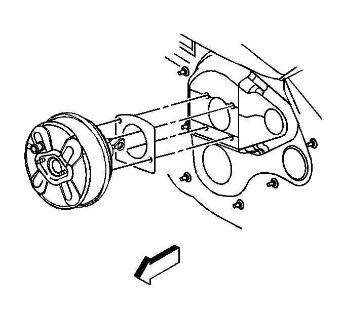
- Remove all related components, including the upper fender rails and the vacuum brake booster. Refer to Front Fender Upper Rail Replacement and Power Vacuum Brake Booster Replacement in Hydraulic Brakes.
- Repair as much of the damage as possible to factory specifications.
- Note the location and remove the sealers and anti-corrosion materials from the repair area, as necessary. Refer to Anti-Corrosion Treatment and Repair in Paint and Coatings.
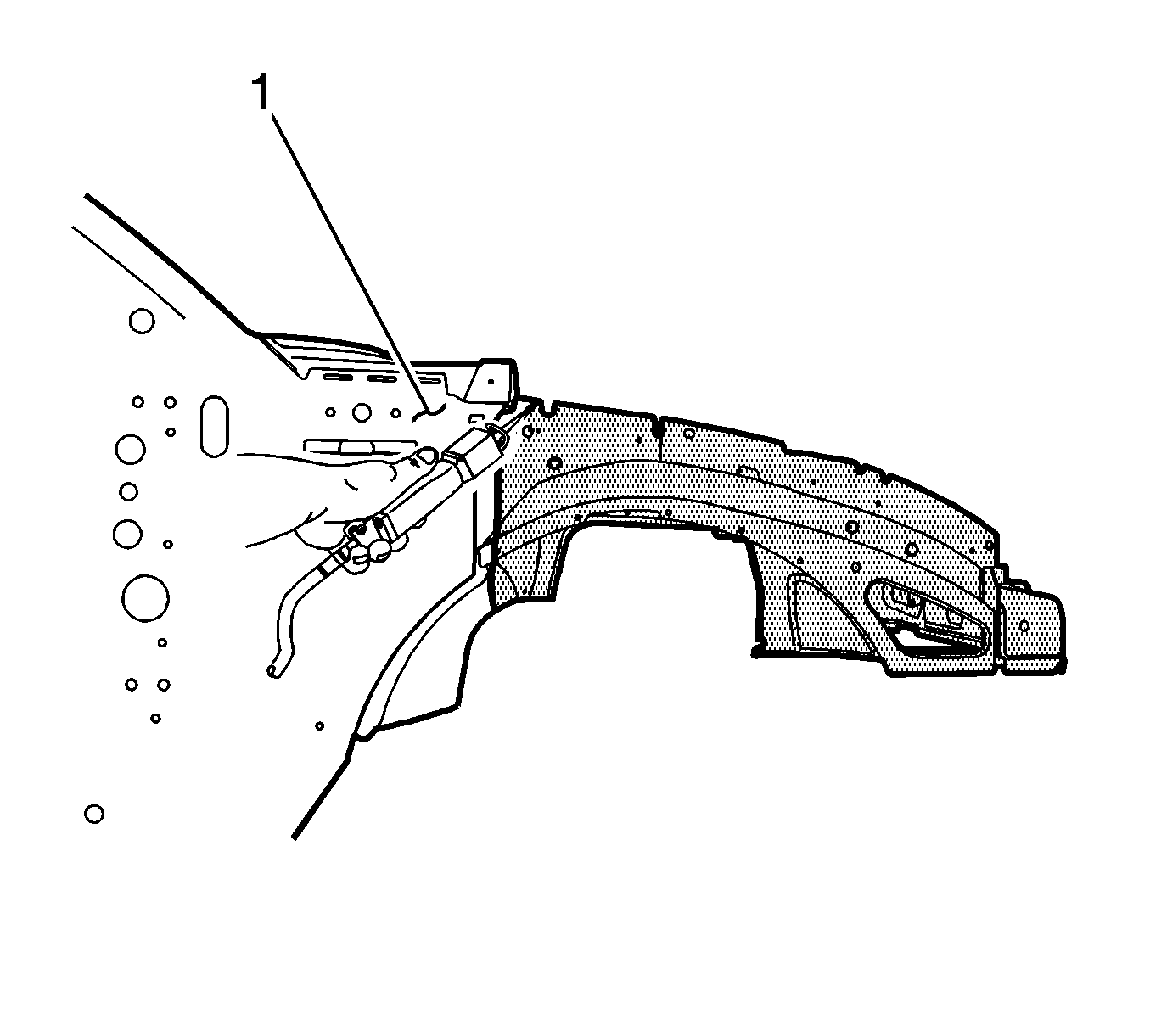
- With a reciprocating saw or equivalent, cut both the right and the left wheelhouse panel assemblies approximately 26 mm (1 in) in front of the body side panel (1) as shown.
- Remove the 2 body mount bolts from the front tie bar.
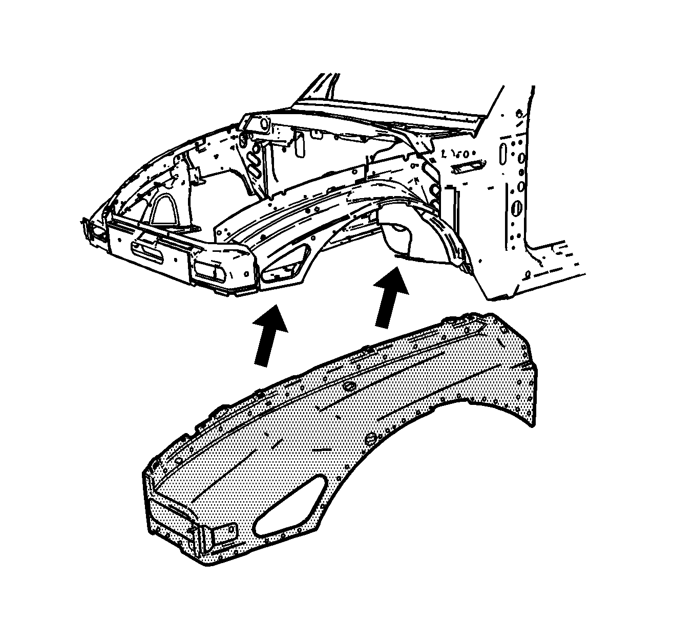
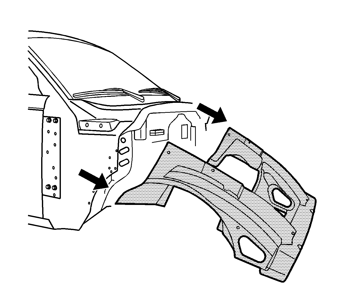
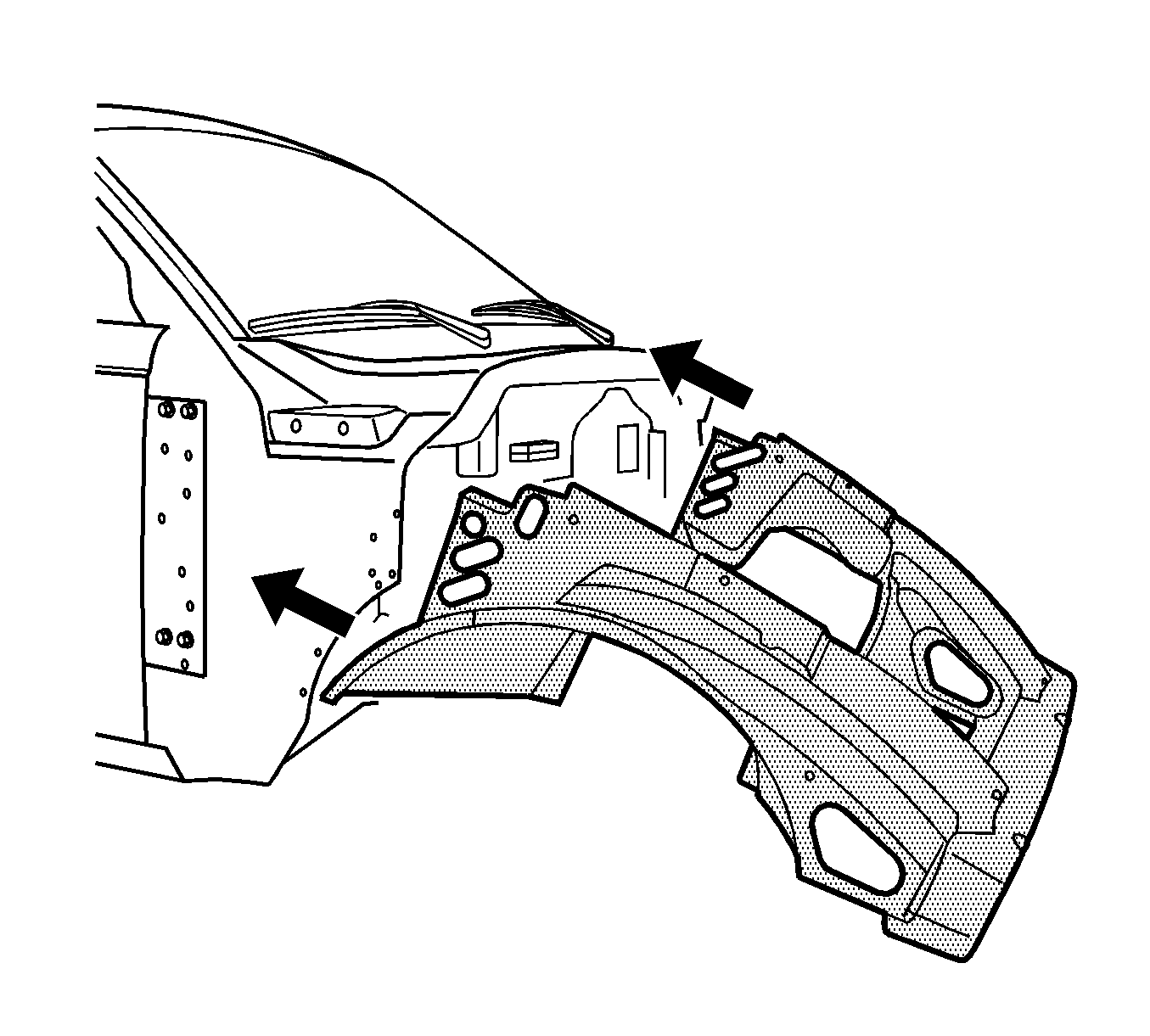
- With the aid of an assistant, remove the damaged front end assembly.
- Locate and drill completely through all factory welds on both the right and the left inboard apron extensions as shown.
- Locate and drill out all factory welds on both the right and the left lower wheelhouse outboard extension (1).
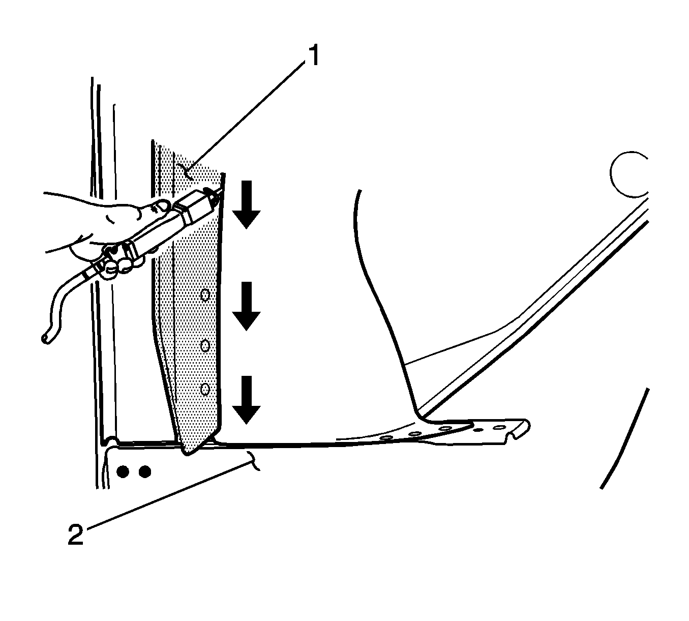
- With a reciprocating saw or equivalent, and using the outboard wheelhouse extension (1) as a guide, cut along the side of the extension down to the floor crossmember (2) as shown.
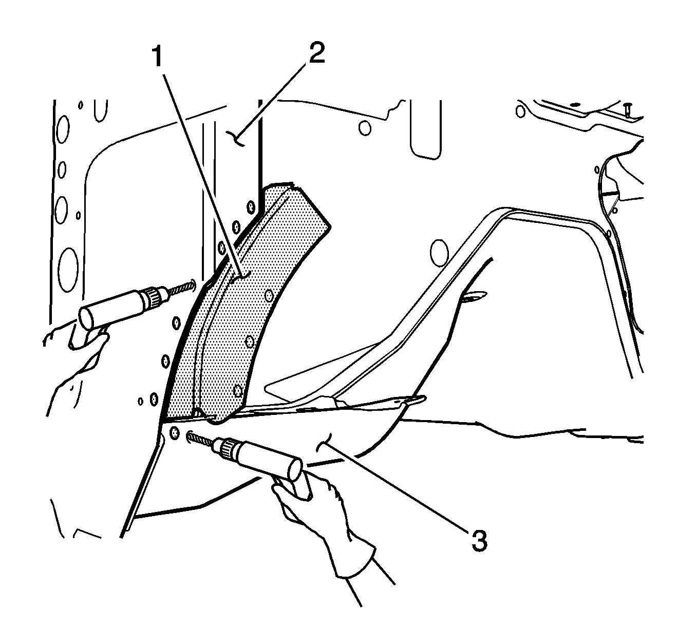
- Locate and drill completely through all factory welds which attach the right and the left outboard wheelhouse extensions (1) to the body side panel (2) and to the front floor crossmember (3).
- Remove and discard the outboard wheelhouse extensions.
- Cut a slot into the wheelhouse panel (1) approximately 152 mm (6 in) above the front floor crossmember (2).
- Apply ¾ in masking tape from the slot (1) up and around the plenum (2) as shown. Line up the front edge of the tape with the back edge of the remaining holes in the wheelhouse panel.
- With a cut-off wheel or equivalent, cut the remaining portions of the wheelhouse panels along the front edge of the masking tape as shown.
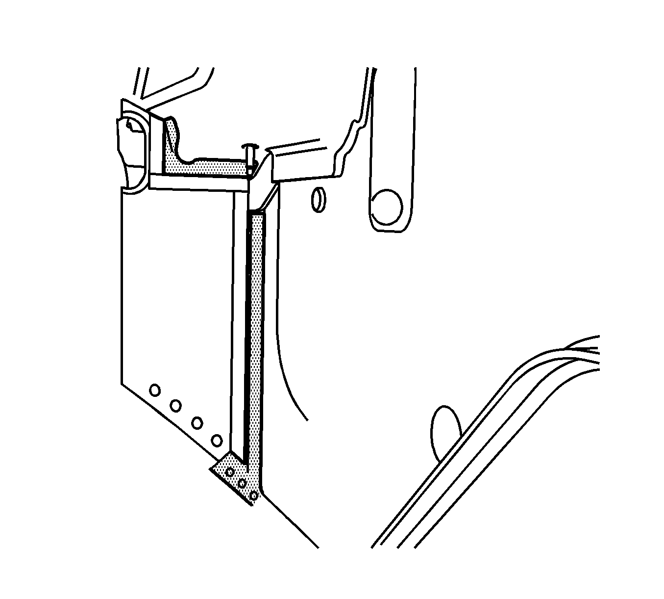
- Remove and discard the wheelhouse panels.
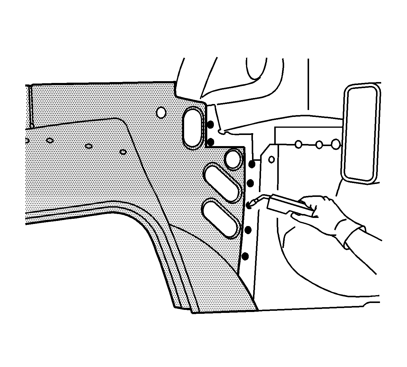
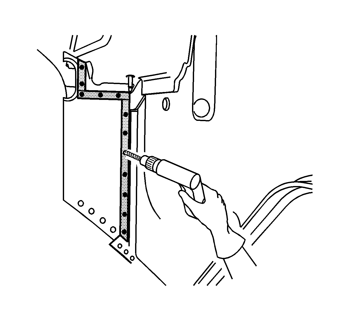
- Drill 8 mm (5/16 in) plug weld holes approximately 26 mm (1 in) apart in both the right and the left weld flanges as shown.
- Prepare all mating surfaces as necessary.
- Apply 3M® Weld-Thru Coating P/N 05916 or equivalent to all mating surfaces.
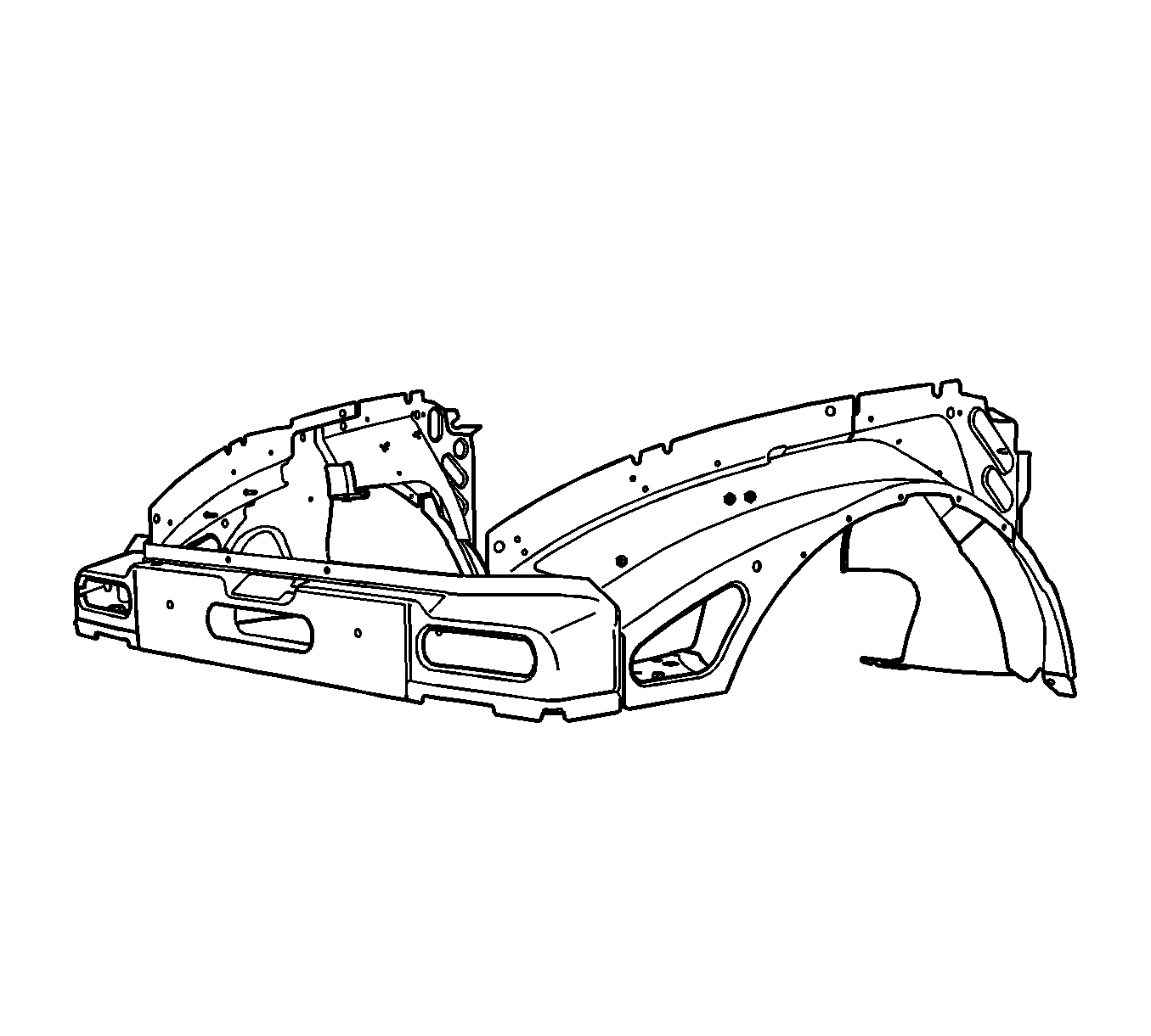
Important: The replacement front end kit is serviced as a complete assembly. Parts with the front end kit include the front tie bar assembly, the left and the right front wheelhouse assemblies, and an instruction sheet.
You must remove and replace the upper fender rails in order to replace the front end kit. The upper fender rails are not included in the front end kit and must be ordered separately.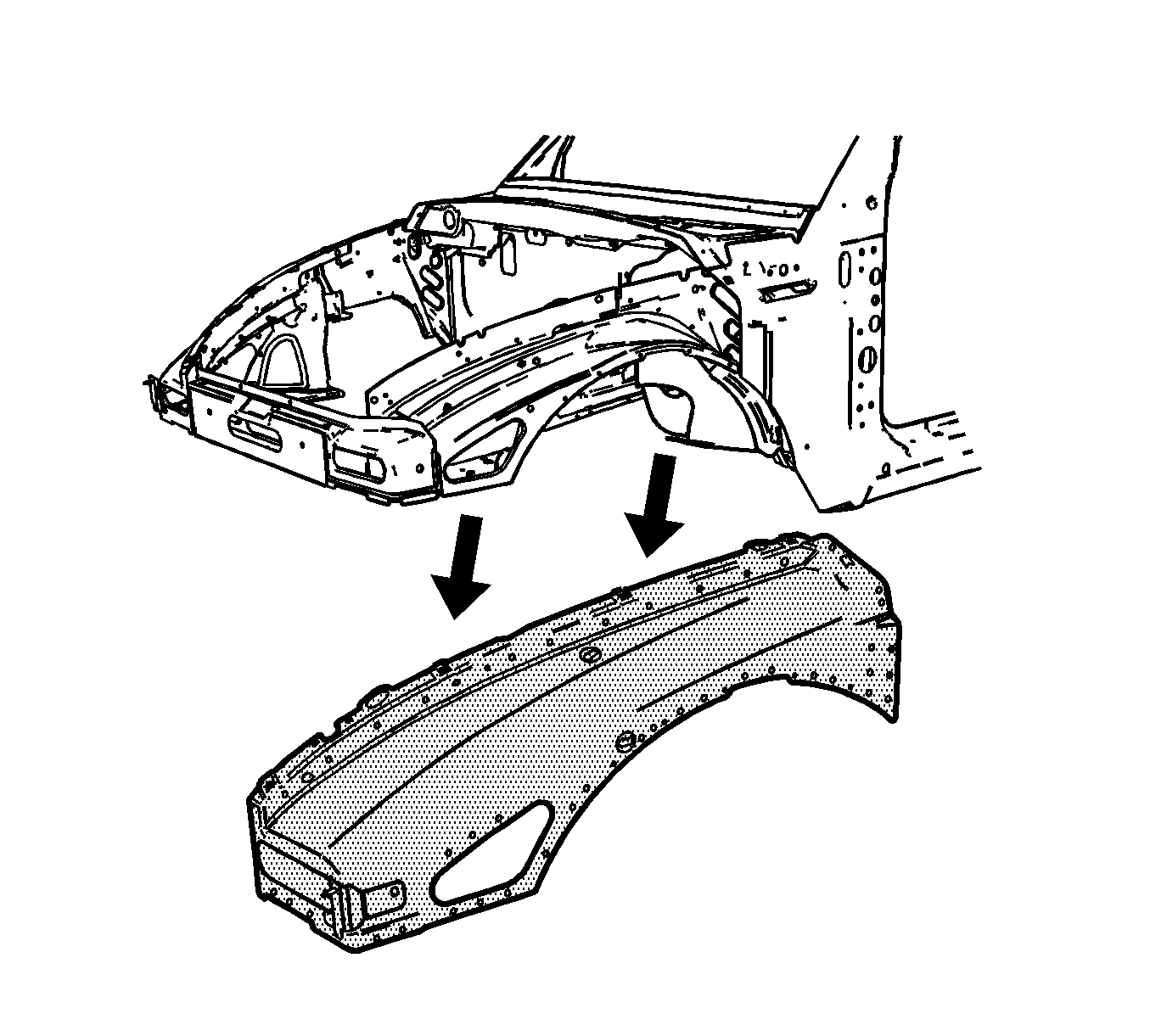
Caution: Refer to Approved Equipment for Collision Repair Caution in the Preface section.
Caution: Refer to Foam Sound Deadeners Caution in the Preface section.
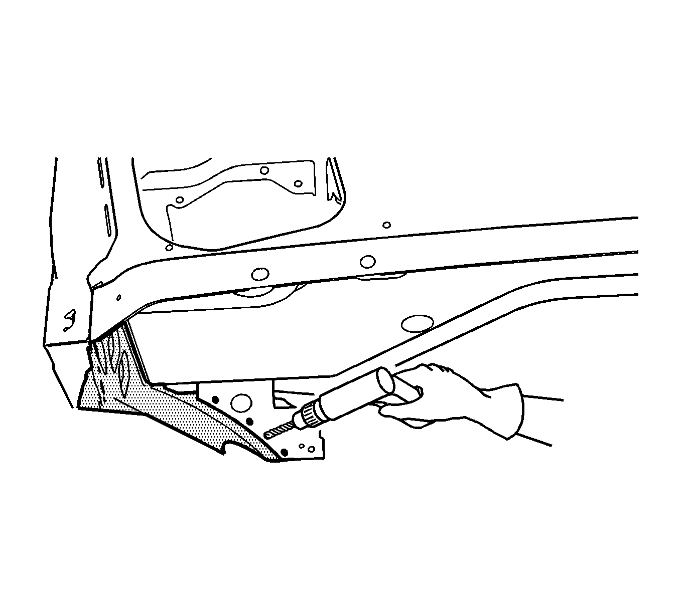
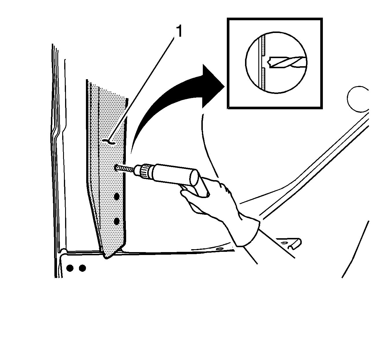
Important: Do NOT drill into the wheelhouse panel.
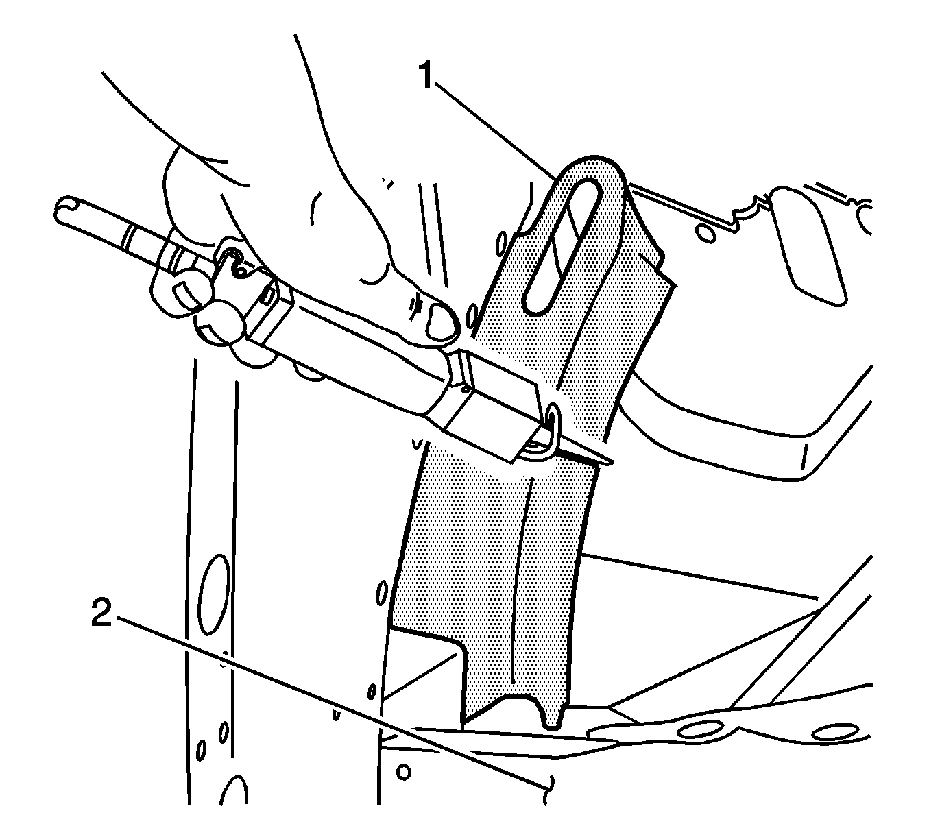
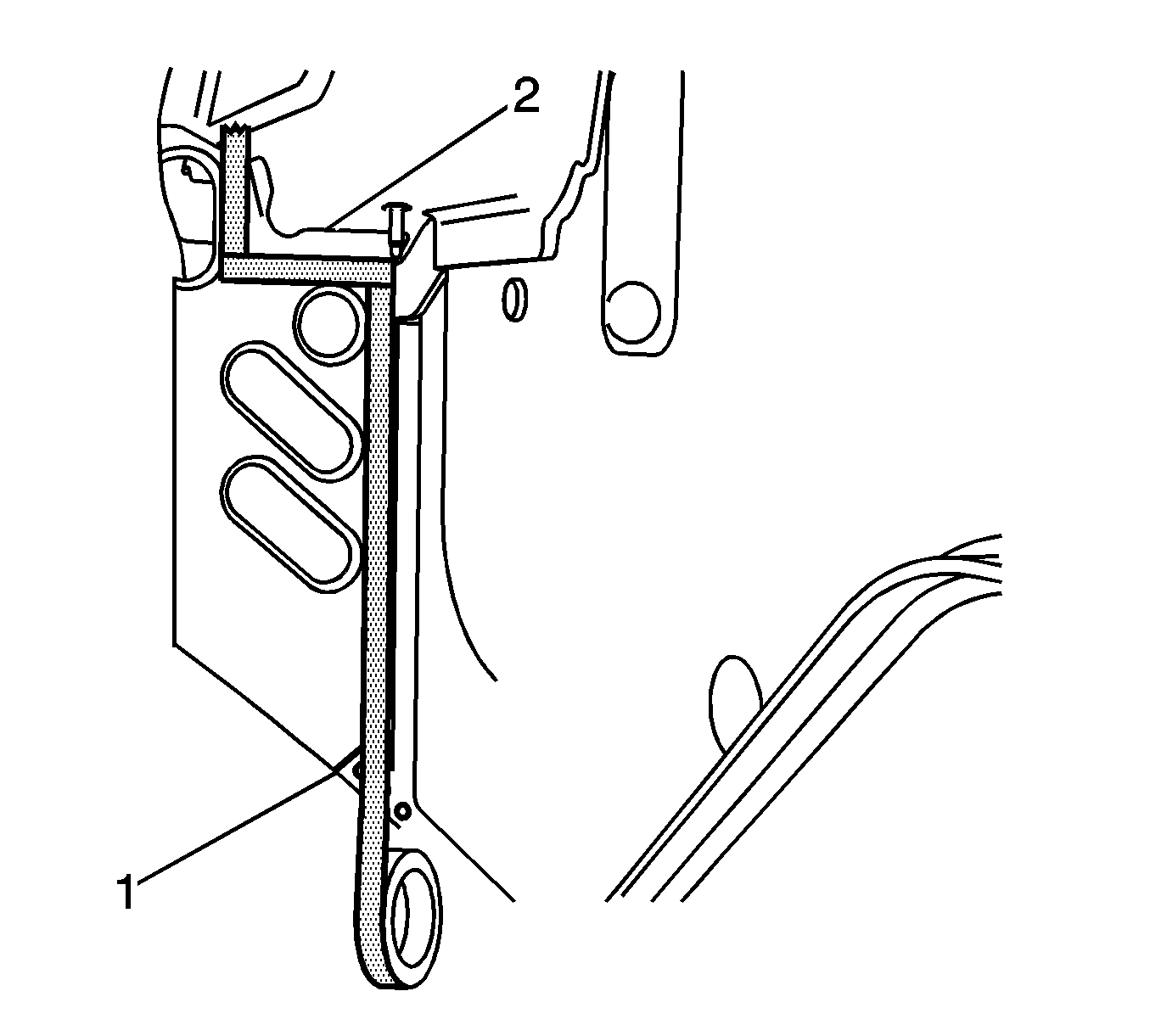
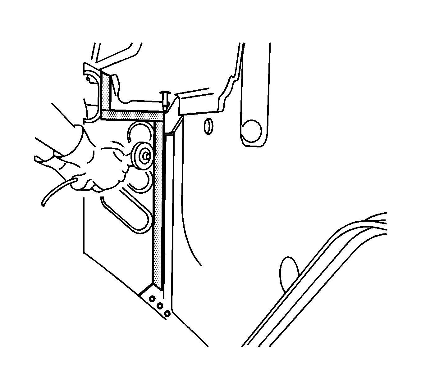
Important: The tape edge facing the front of the vehicle is the proper cut location to create a weld flange for the service front end assembly.
Service Part Preparations
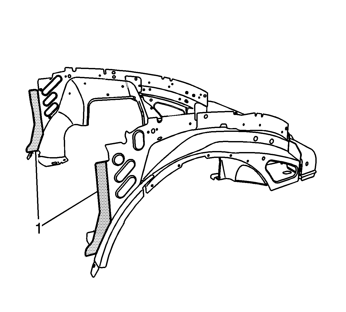
Important: Trim the backs of both wheelhouse panels (1) to create the proper size weld flange for installation of the service front end kit.
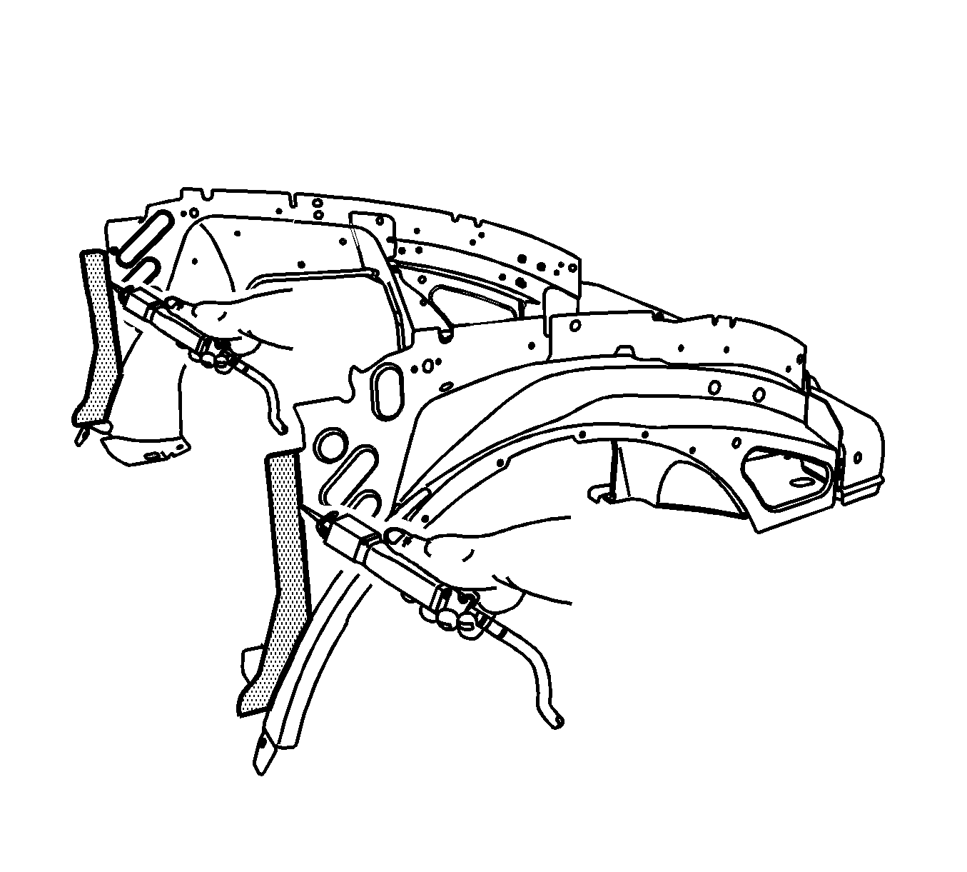
- Using a reciprocating saw or equivalent, remove approximately 38 mm (1.5 in) of the back of each wheelhouse panel as shown.
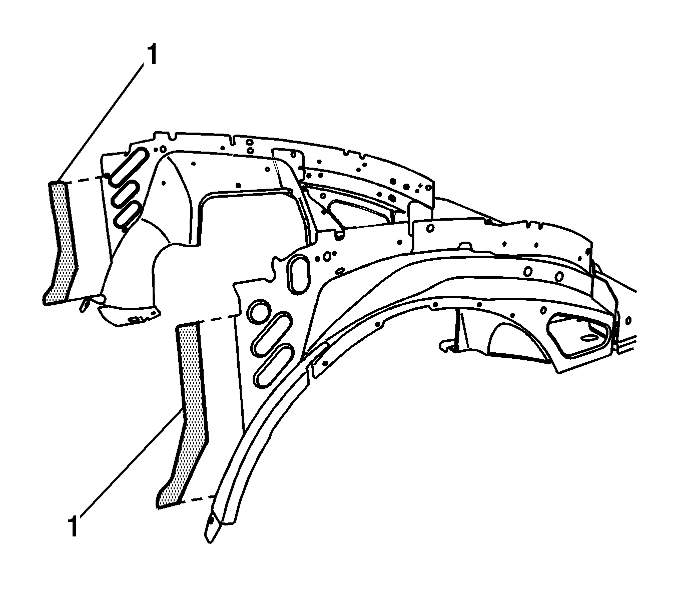
- Remove and discard the trimmed wheelhouse flanges (1).
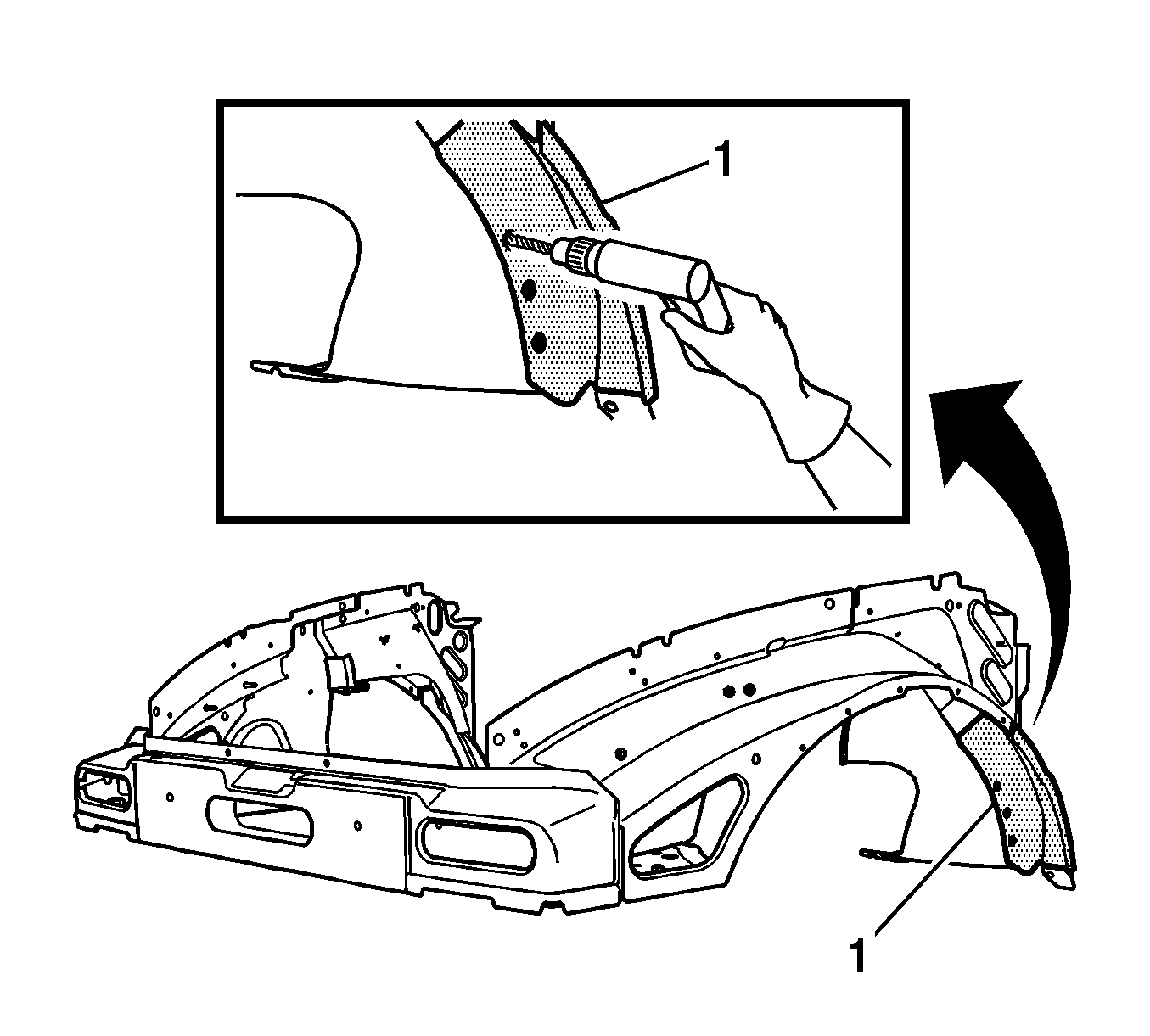
- Locate and drill completely through all factory welds on both of the wheelhouse panel extensions (1). The left panel is shown, the right panel is similar.
- Prepare all mating surfaces as necessary.
- Apply 3M® Weld-Thru Coating P/N 05916 or equivalent to all mating surfaces.
Installation Procedure
- With the aid of an assistant, position the service front end assembly and clamp the assembly in place. Inspect for proper positioning. Refer to Motor Compartment in Dimensions - Body .
- Reinstall the 2 body mount bolts from the front tie bar.
- Plug weld accordingly.
- Install the upper fender rails. Refer to Front Fender Upper Rail Replacement .
- Clean and prepare all welded surfaces.
- Apply the sealers and the anti-corrosion materials to the repair area, as necessary. Refer to Anti-Corrosion Treatment and Repair in Paint and Coatings.
- Paint the repair area. Refer to Basecoat/Clearcoat Paint Systems in Paint and Coatings.
- Install all related components, including the vacuum booster. Refer to Power Vacuum Brake Booster Replacement in Hydraulic Brakes.
- Connect the negative battery cable. Refer to Battery Negative Cable Disconnection and Connection in Engine Electrical.
- Enable the SIR system. Refer to SIR Disabling and Enabling in SIR.
Tighten
Tighten the bolts to 140 N·m (103 lb ft).
