Removal Procedure
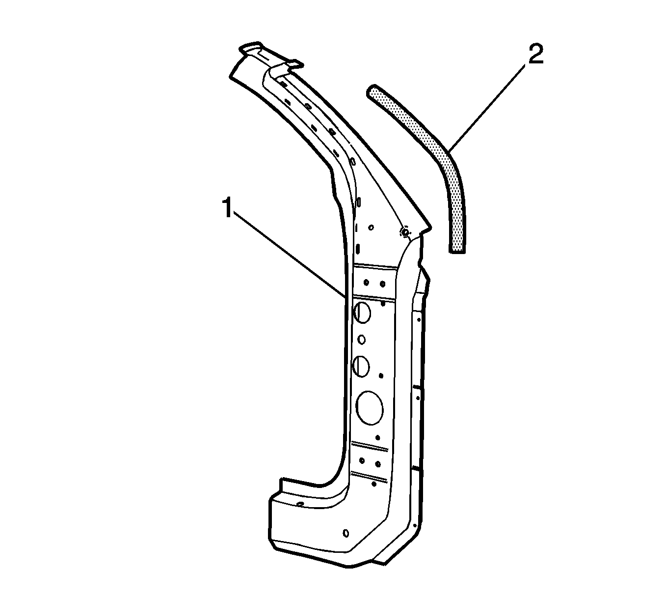
Important: The inner hinge pillar reinforcement assembly (1) includes a high-strength low-alloy (HSLA) A-pillar reinforcement tube (2). Cold working is preferred when straightening damaged HSLA steel components. The application of heat may soften the steel and should be avoided whenever possible. If the use of heat is required in the repair of structural components, the temperature should not exceed 654°C (1200°F). Use temperature indicating crayons to assure that this temperature limit is not exceeded.
Do NOT expose HSLA steel to the maximum temperature for more than 3 minutes. Apply rust proofing materials to both sides of any surface that has been heated enough to damage the factory coatings.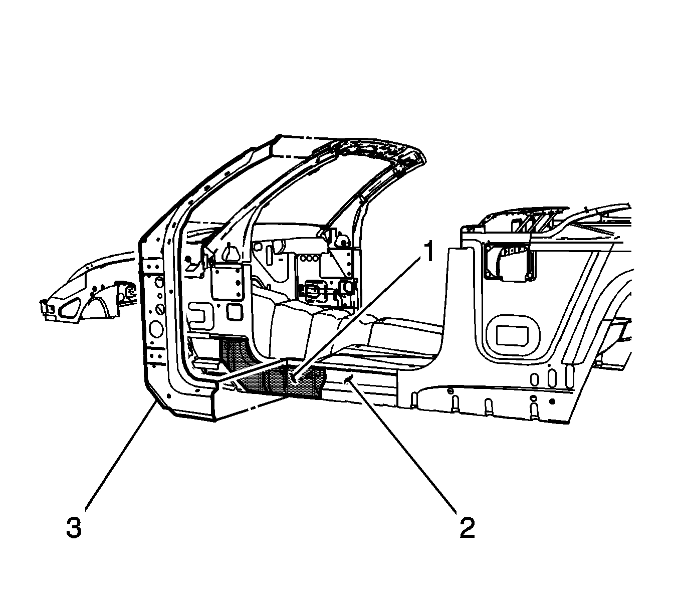
Important: Structural foam (1) is located between the inner rocker (2) and the inner hinge pillar reinforcements (3) on both the right and the left side of the vehicle. Precast structural foam replacement blocks are available if necessary, and can be ordered separately.
Failure to replace any damaged structure foam reinforcement as described could compromise the structural integrity of the vehicle. Refer to Structure Foam Replacement .- Disable the SIR system. Refer to SIR Disabling and Enabling in SIR.
- Disconnect the negative battery cable. Refer to Battery Negative Cable Disconnection and Connection in Engine Electrical.
- Remove all related panels and components, including the body side panel. Refer to Body Side Outer Panel Replacement or to Body Side Outer Panel Sectioning .
- Repair as much of the damage as possible to factory specifications. Refer to Windshield Opening and Door Opening in Dimensions - Body .
- Note the location and remove the sealers and anti-corrosion materials from the repair area, as necessary. Refer to Anti-Corrosion Treatment and Repair in Paint and Coatings.
- Locate and drill out all factory welds and rivets. Note the number and location of welds for installation of the service inner hinge pillar.
- Verify the existence of structural weld-through adhesive. Refer to Structure Adhesive Identification . If necessary use a chisel to separate the outer header panel from the inner header panel.
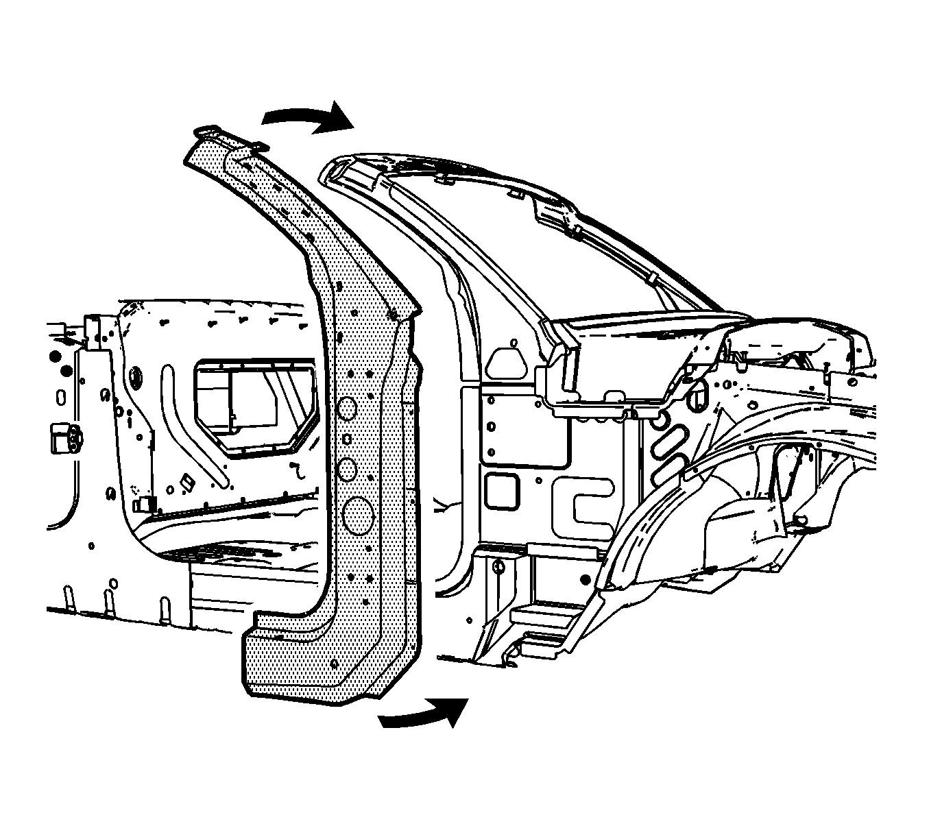
- Remove the damaged inner hinge pillar.
Caution: Refer to Approved Equipment for Collision Repair Caution in the Preface section.
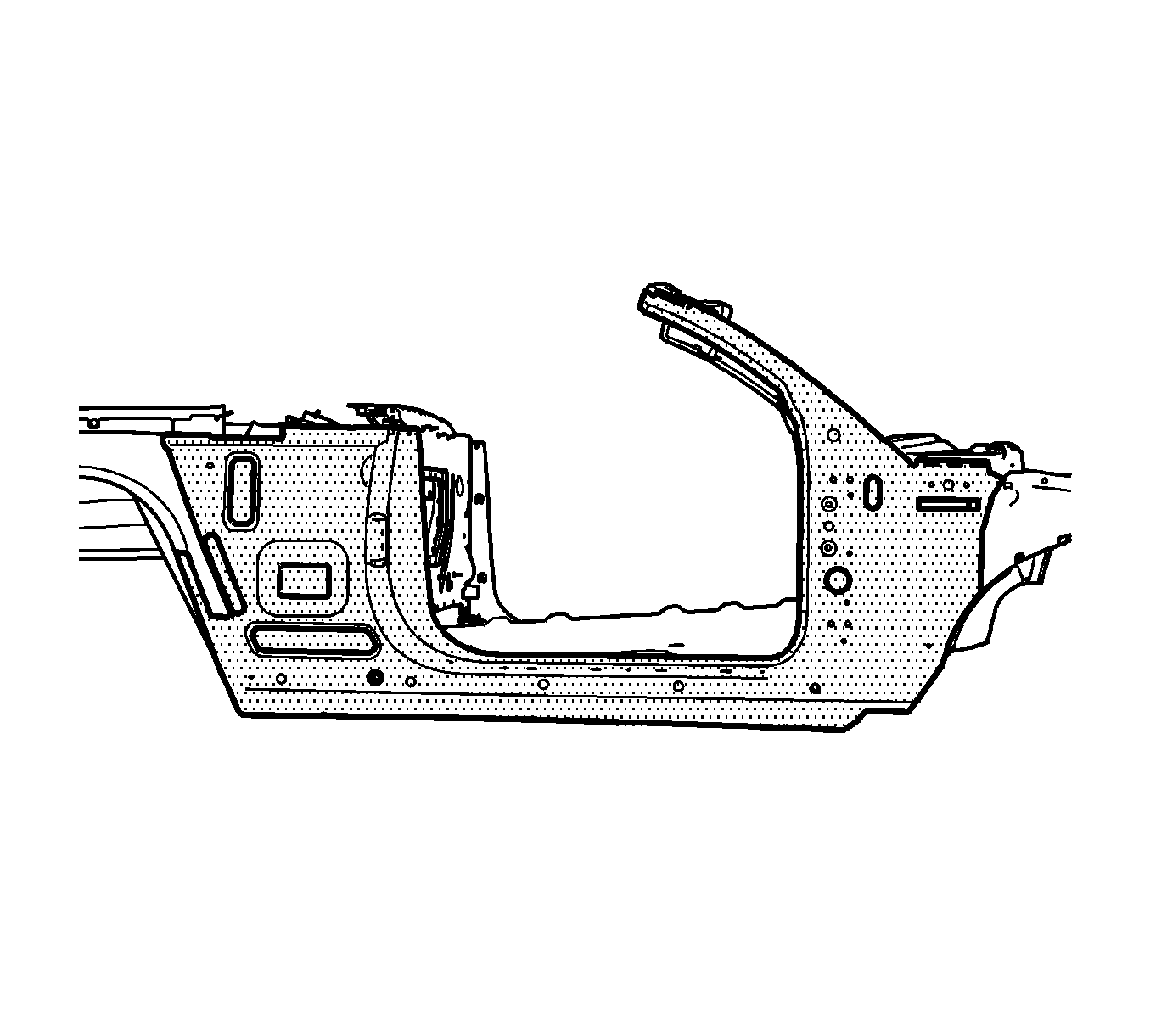
Caution: Refer to Foam Sound Deadeners Caution in the Preface section.
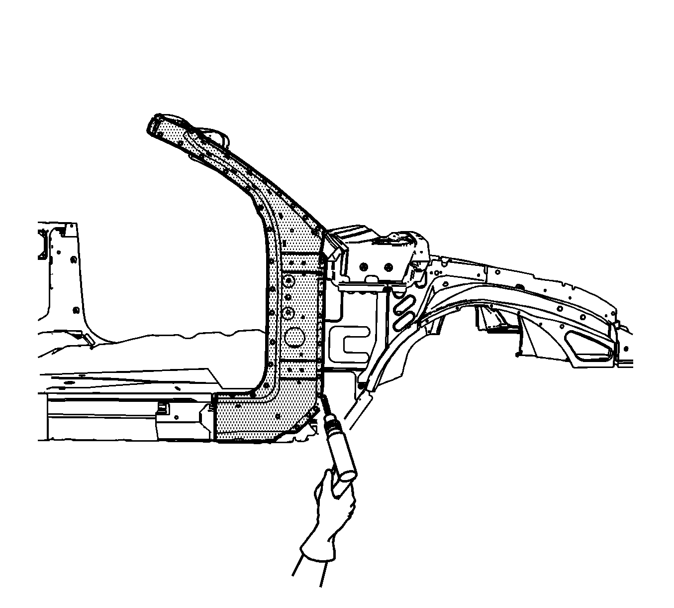
Important: Do not damage any inner panels or reinforcements.
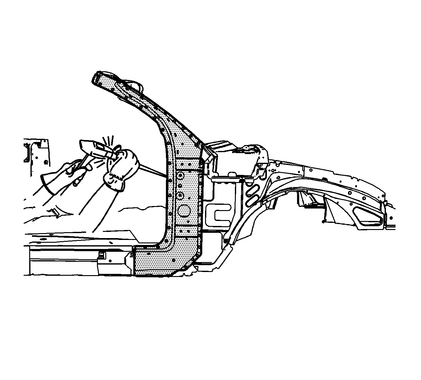
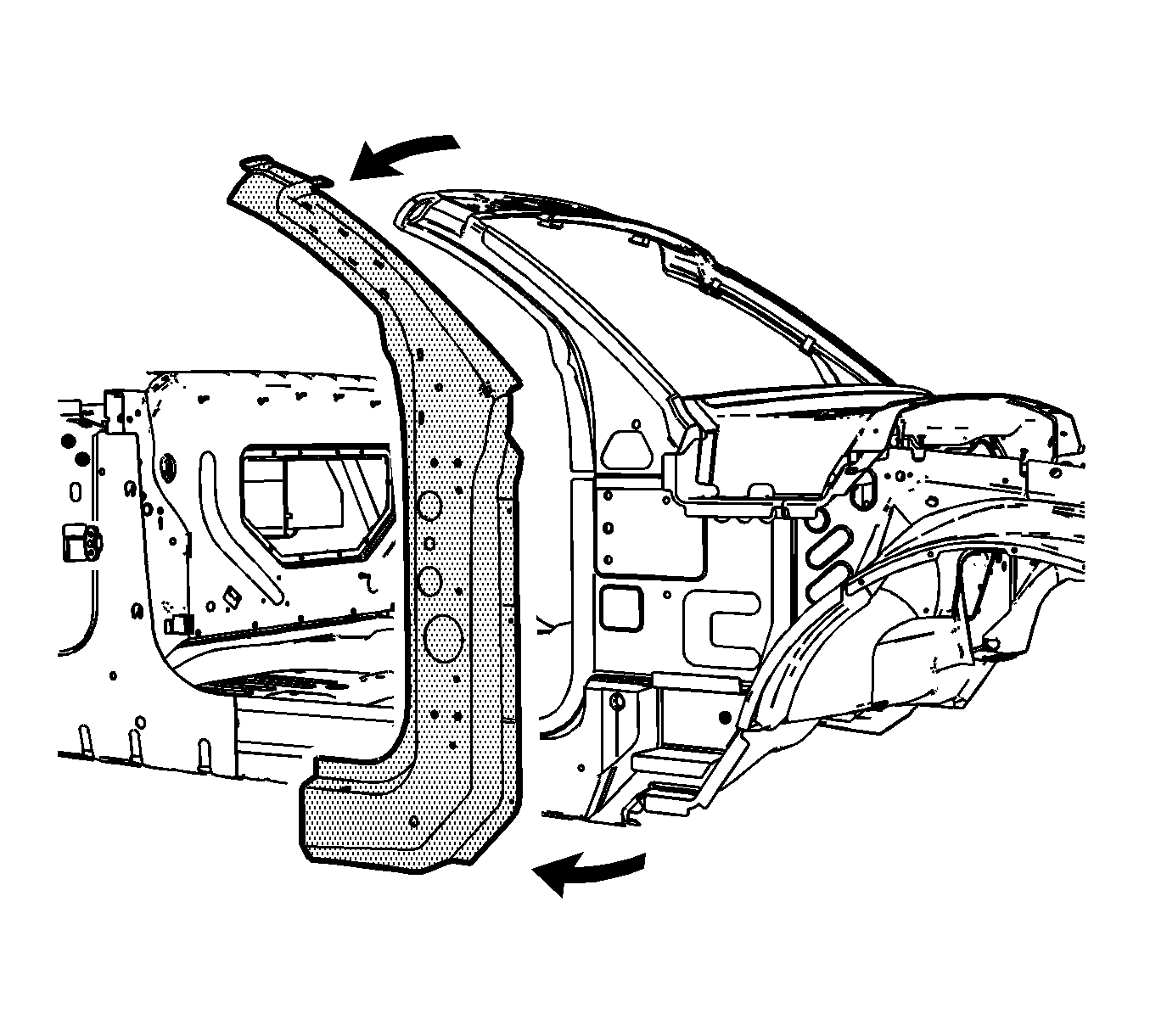
Important: Do NOT damage the structural foam reinforcement block when you remove the inner hinge pillar.
Installation Procedure
- Drill 8 mm (5/16 in) plug weld holes in the service part as necessary at the locations noted from the original inner reinforcement.
- Drill 8 mm (5/16 in) plug weld holes in the service part as necessary in the following locations:
- Replace the structural adhesive with an additional plug weld between the existing plug welds, where necessary.
- Prepare all mating surfaces as necessary.
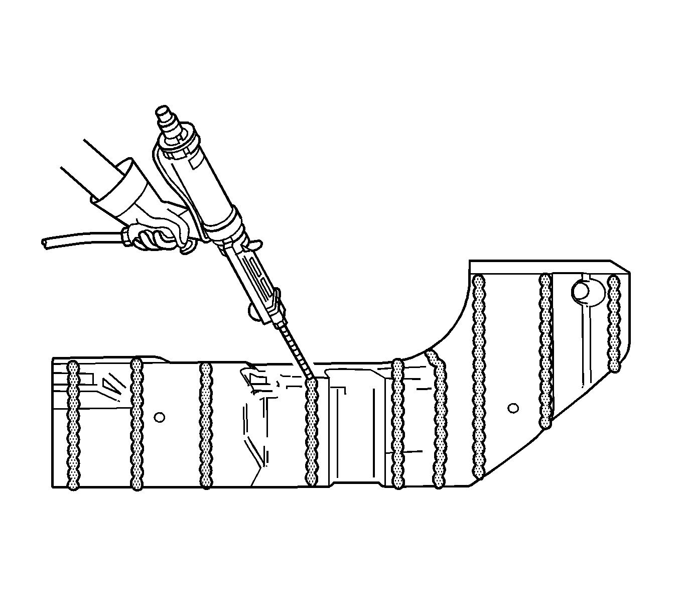
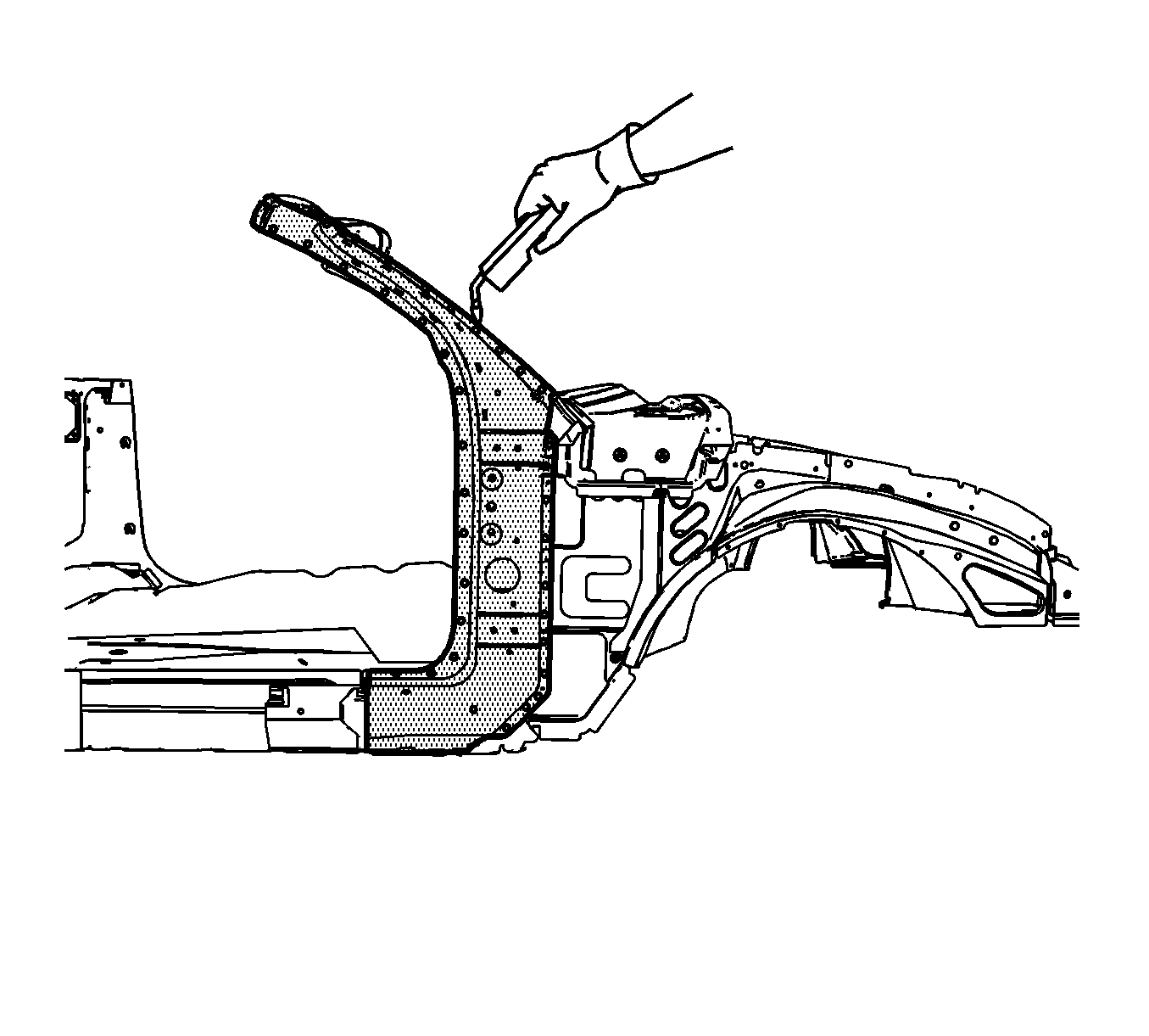
- Apply 3M® Weld-Thru coating P/N 05916 or equivalent to all mating surfaces.
- Inspect the structural foam block for damage and replace the block if necessary. Refer to Structure Foam Replacement .
- Position the inner hinge pillar reinforcement. Refer to Windshield Opening and Door Opening in Dimensions - Body .
- Plug weld accordingly.
- Install all related panels, including the body side panel. Refer to Body Side Outer Panel Replacement or to Body Side Outer Panel Sectioning .
- Clean and prepare all welded surfaces.
- Apply the sealers and anti-corrosion materials to the repair area, as necessary. Refer to Anti-Corrosion Treatment and Repair in Paint and Coatings.
- Paint the repair area. Refer to Basecoat/Clearcoat Paint Systems in Paint and Coatings.
- Install all related components.
- Connect the negative battery cable. Refer to Battery Negative Cable Disconnection and Connection in Engine Electrical.
- Enable the SIR system. Refer to SIR Disabling and Enabling in SIR.
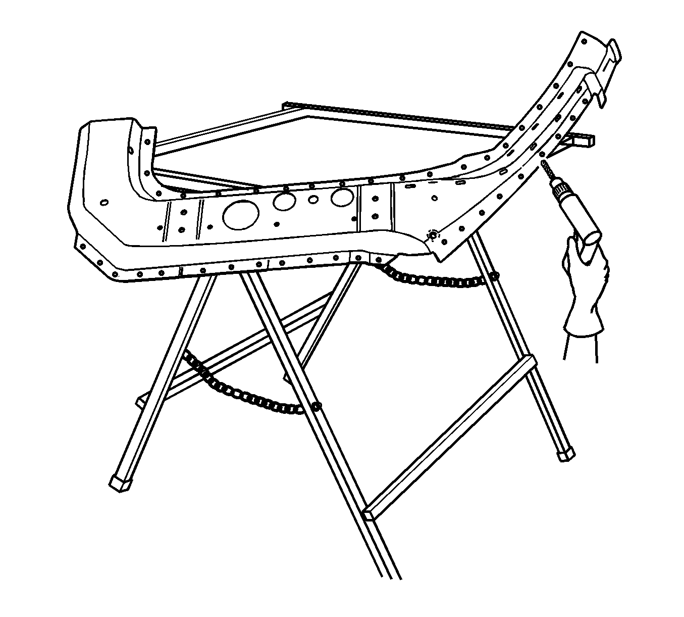
| • | Where the rivets were located. |
| • | Every 40 mm (1 5/8 in) apart along the front weld flange where only structural adhesive was used. |
