GM Service Manual Online
For 1990-2009 cars only
Makes
🢒
Chevrolet
🢒
2004
🢒
SSR
🢒
Brakes
🢒
Hydraulic Brakes
🢒 Engine Controls Schematics
Figure
1:
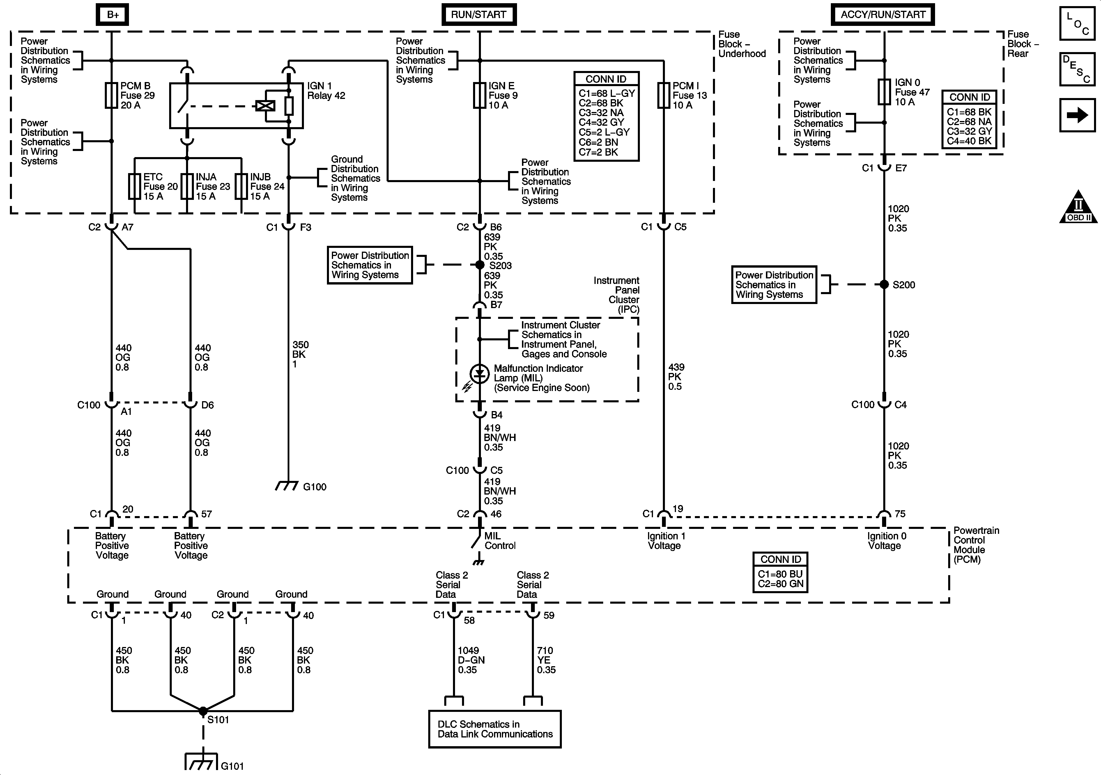
Power, Ground, Serial Data and MIL
Master Electrical Component List
Powertrain Control Module Description
Engine Data Sensors - 5 Volts and Low Reference
OBD II Symbol Description Notice
B+ Bus - Fuse Block Underhood
COILS, CANISTER, IPC/DIC, FLASH, TBC1 and PCMB Fuses
G100, G102
ACCY/RUN and RUN/START Bus Bar
IGN E, TBC IGN 1, BCK/UP and BTSI
ACCY/RUN/START, RUN and START Bus Bars
IGN0, TBCIG, TBC 4CC, FT WPR Fuses
IGN E, TBC IGN 1, BCK/UP and BTSI
Power, Ground, Serial Data and MIL
IGN0, TBCIG, TBC 4CC, FT WPR Fuses
G101
Data Link Connector
Figure
2:
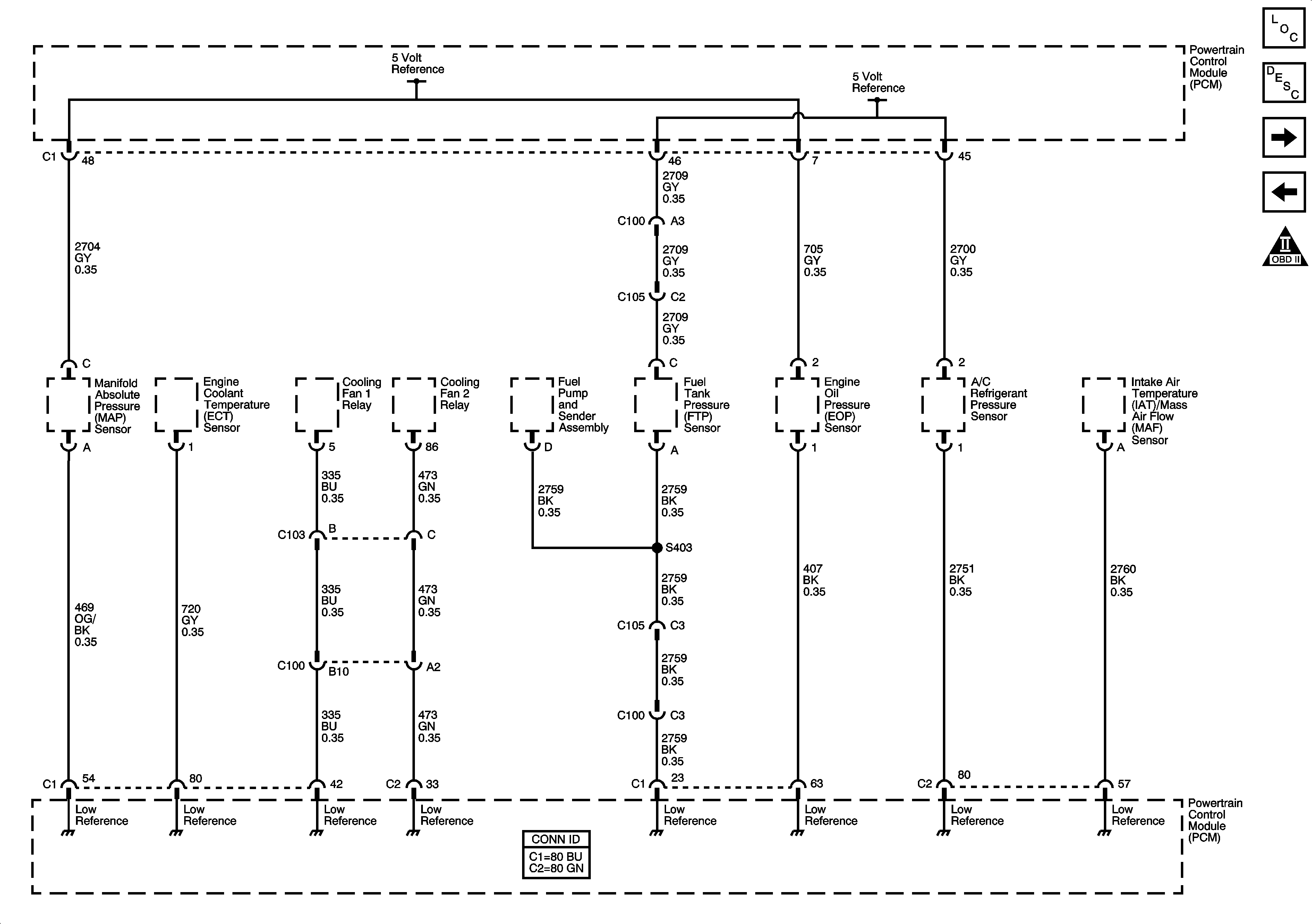
Engine Data Sensors - 5-Volt and Low Reference
Master Electrical Component List
Powertrain Control Module Description
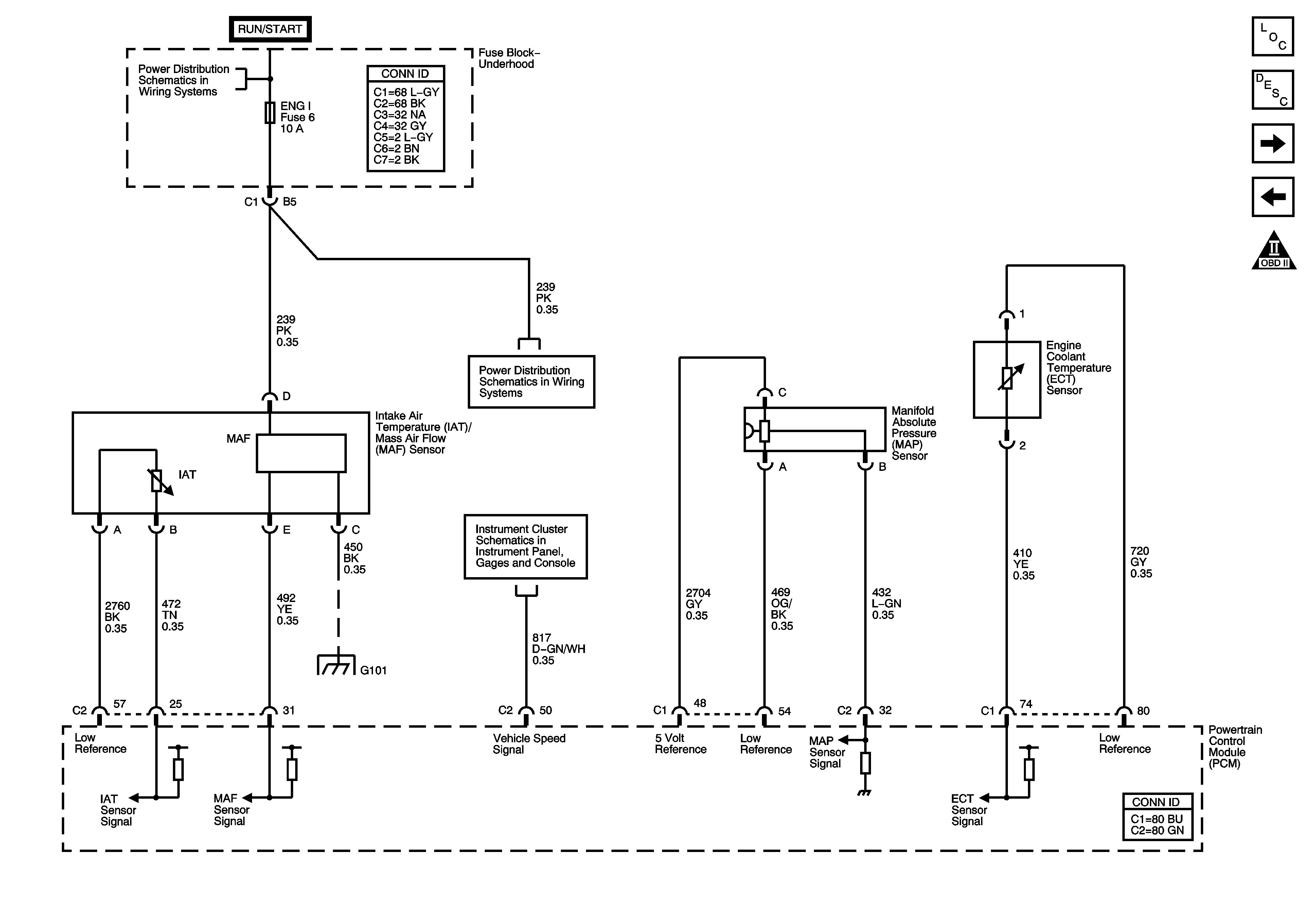
Engine Data Sensors - Pressure, Temperature and VSS
Power, Ground, Serial Data and MIL
OBD II Symbol Description Notice
Figure
3:
Engine Data Sensors - Pressure, Temperature and VSS
Master Electrical Component List
Powertrain Control Module Description
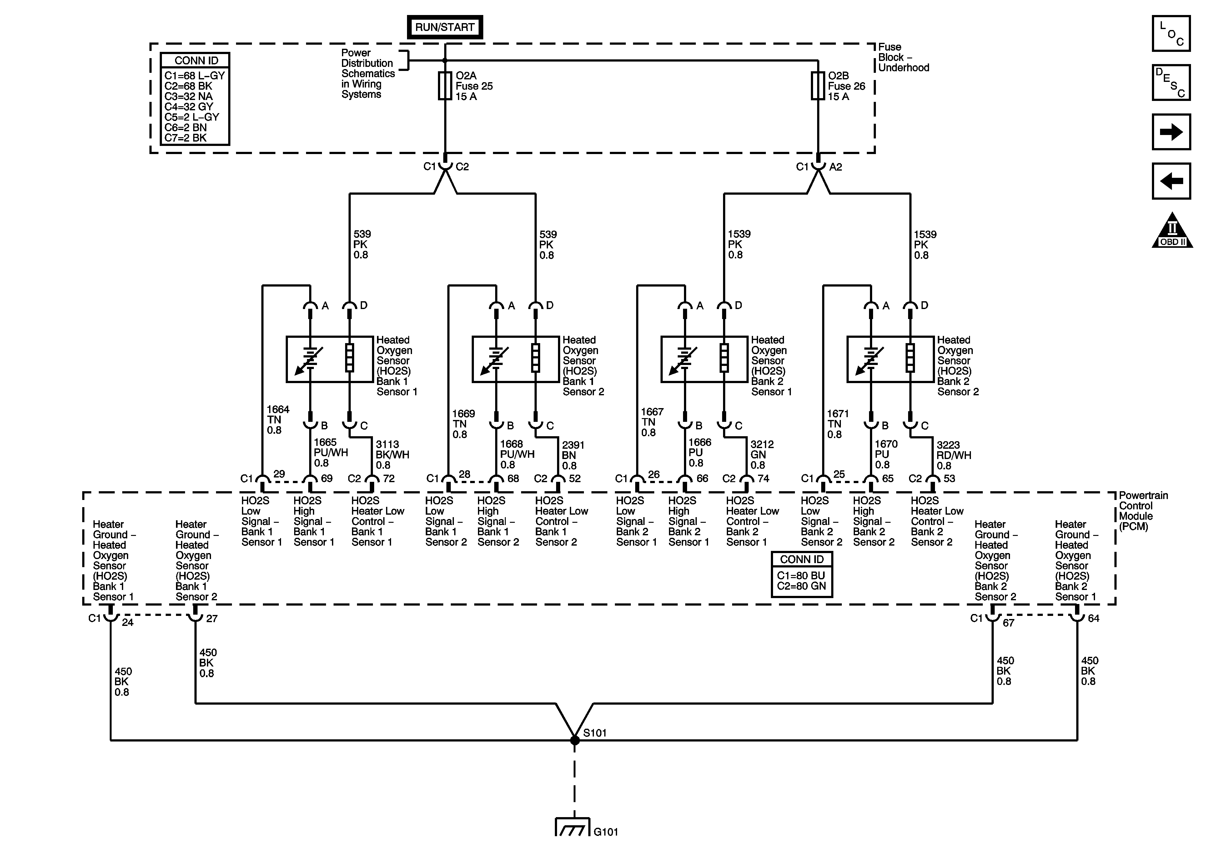
Engine Data Sensors - Oxygen Sensors
Engine Data Sensors - 5 Volts and Low Reference
OBD II Symbol Description Notice
ACCY/RUN and RUN/START Bus Bar
PCM I, SIR, 02A, 02B AND ENG I Fuses
Power, Ground, Serial Data and MIL
G101
Figure
4:
Engine Data Sensors - Oxygen Sensors
Master Electrical Component List
Powertrain Control Module Description
Engine Data Sensors - Throttle Actuator Controls
Engine Data Sensors - Pressure, Temperature and VSS
OBD II Symbol Description Notice
ACCY/RUN and RUN/START Bus Bar
G101
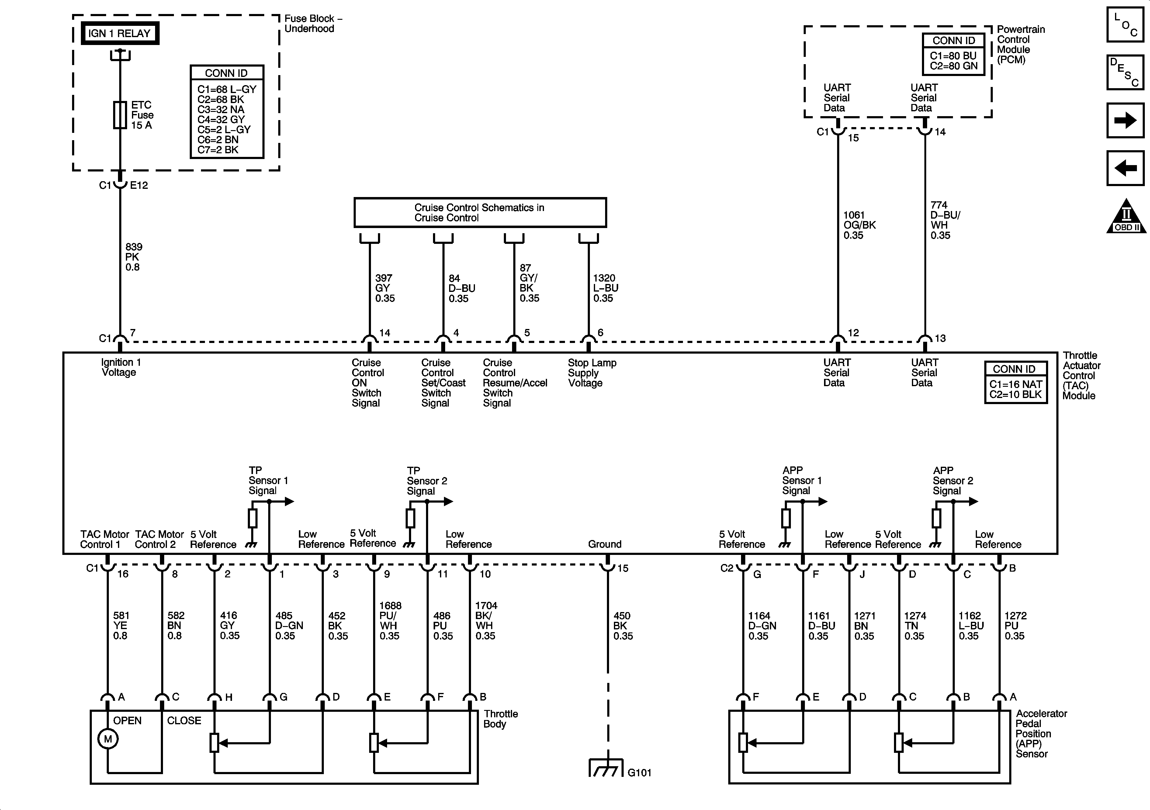
Figure
5:
Engine Data Sensors - Throttle Actuator Controls
Master Electrical Component List
Powertrain Control Module Description
Ignition Coils - Ignition System Coils 1, 3, 5, 7
Engine Data Sensors - Oxygen Sensors
OBD II Symbol Description Notice
Power, Ground, Serial Data and MIL
Power, Ground, TAC Module, APP Sensor and Throttle Body
G101
Figure
6:
Engine Data Sensors - Ignition Controls - Ignition System Coils 1, 3, 5, 7
Master Electrical Component List
Powertrain Control Module Description
Ignition Coils - Ignition System Coils 2, 4, 6, 8
Engine Data Sensors - Throttle Actuator Controls
OBD II Symbol Description Notice
Power, Ground, Serial Data and MIL
TAC, INJA and INJB Fuses
G100, G102
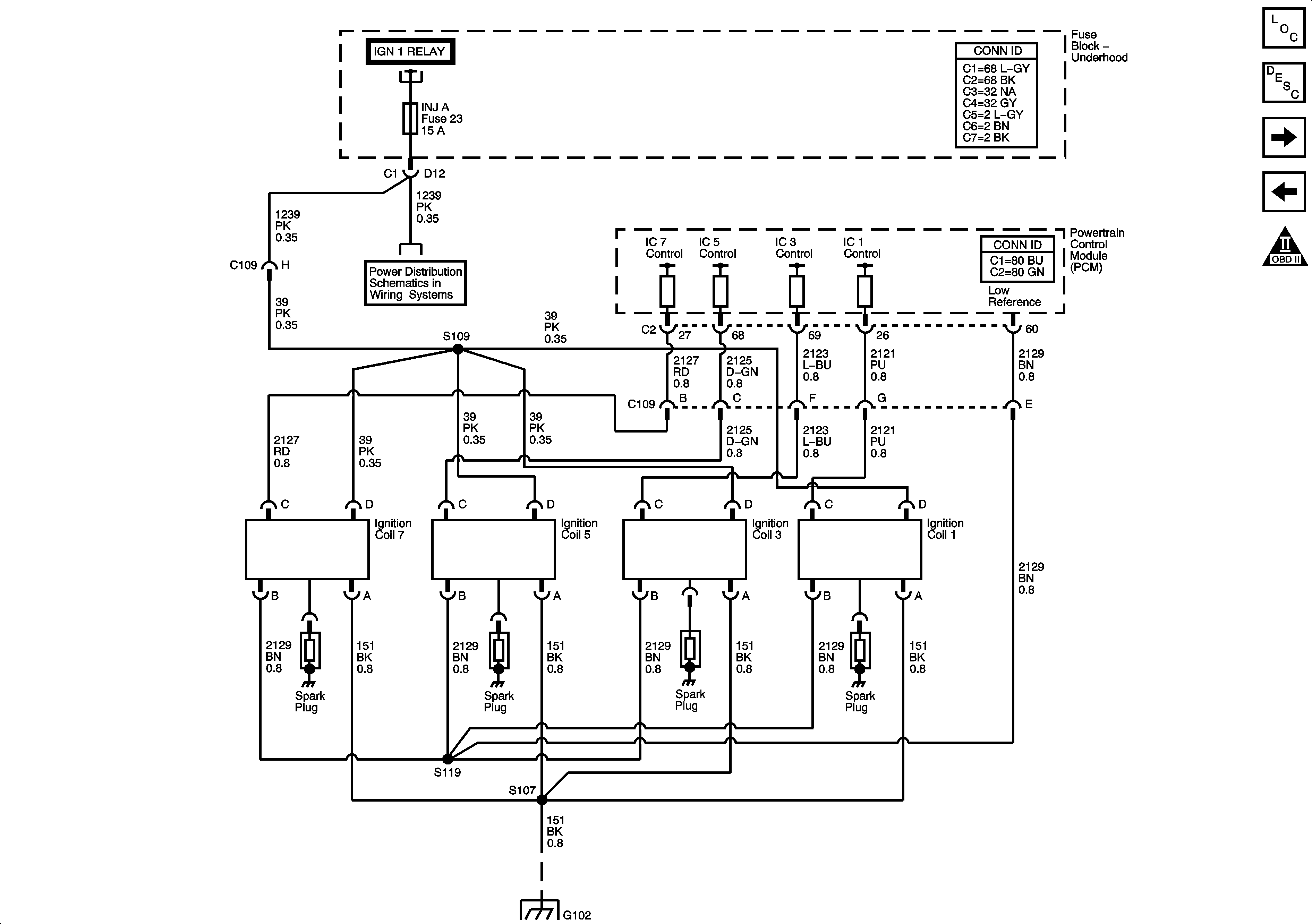
Figure
7:
Engine Data Sensors - Ignition Controls - Ignition System Coils 2, 4, 6, 8
Master Electrical Component List
Powertrain Control Module Description
Ignition Controls - Sensors
Ignition Coils - Ignition System Coils 1, 3, 5, 7
OBD II Symbol Description Notice
Power, Ground, Serial Data and MIL
TAC, INJA and INJB Fuses
G100, G102
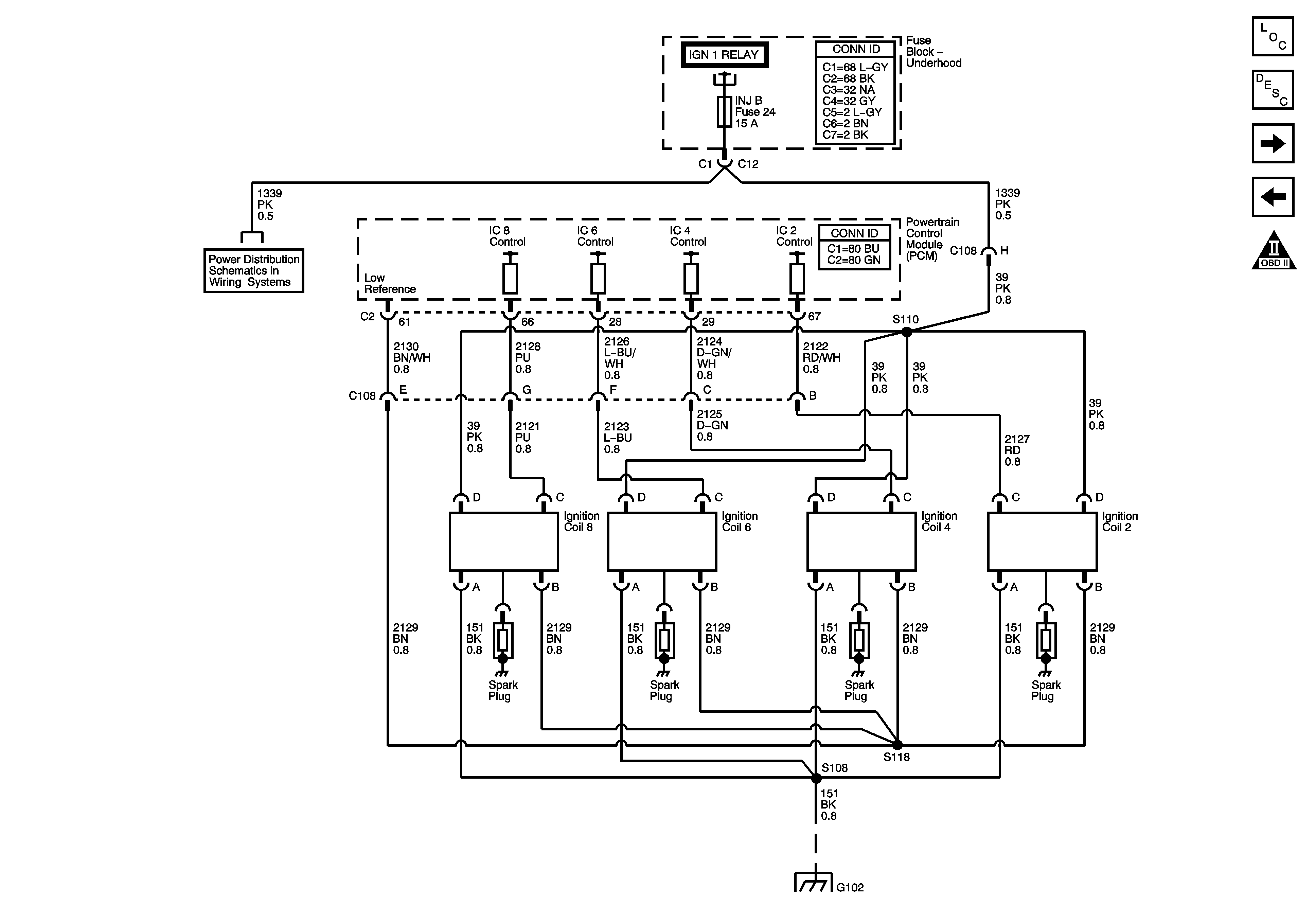
Figure
8:
Engine Data Sensors - Ignition Controls - Sensors
Master Electrical Component List
Powertrain Control Module Description
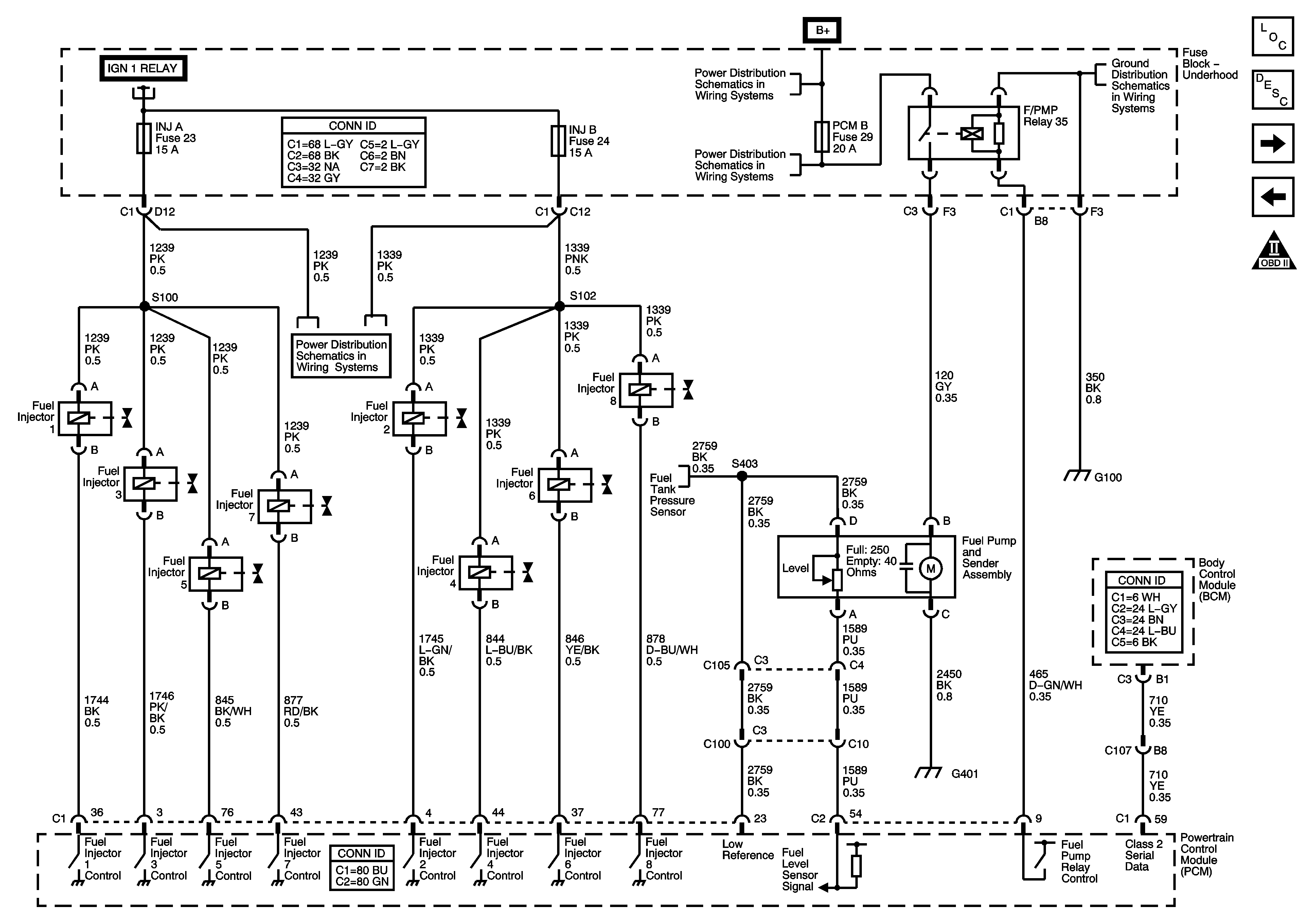
Fuel Controls - Fuel Pump Controls and Fuel Injectors
Ignition Coils - Ignition System Coils 2, 4, 6, 8
OBD II Symbol Description Notice
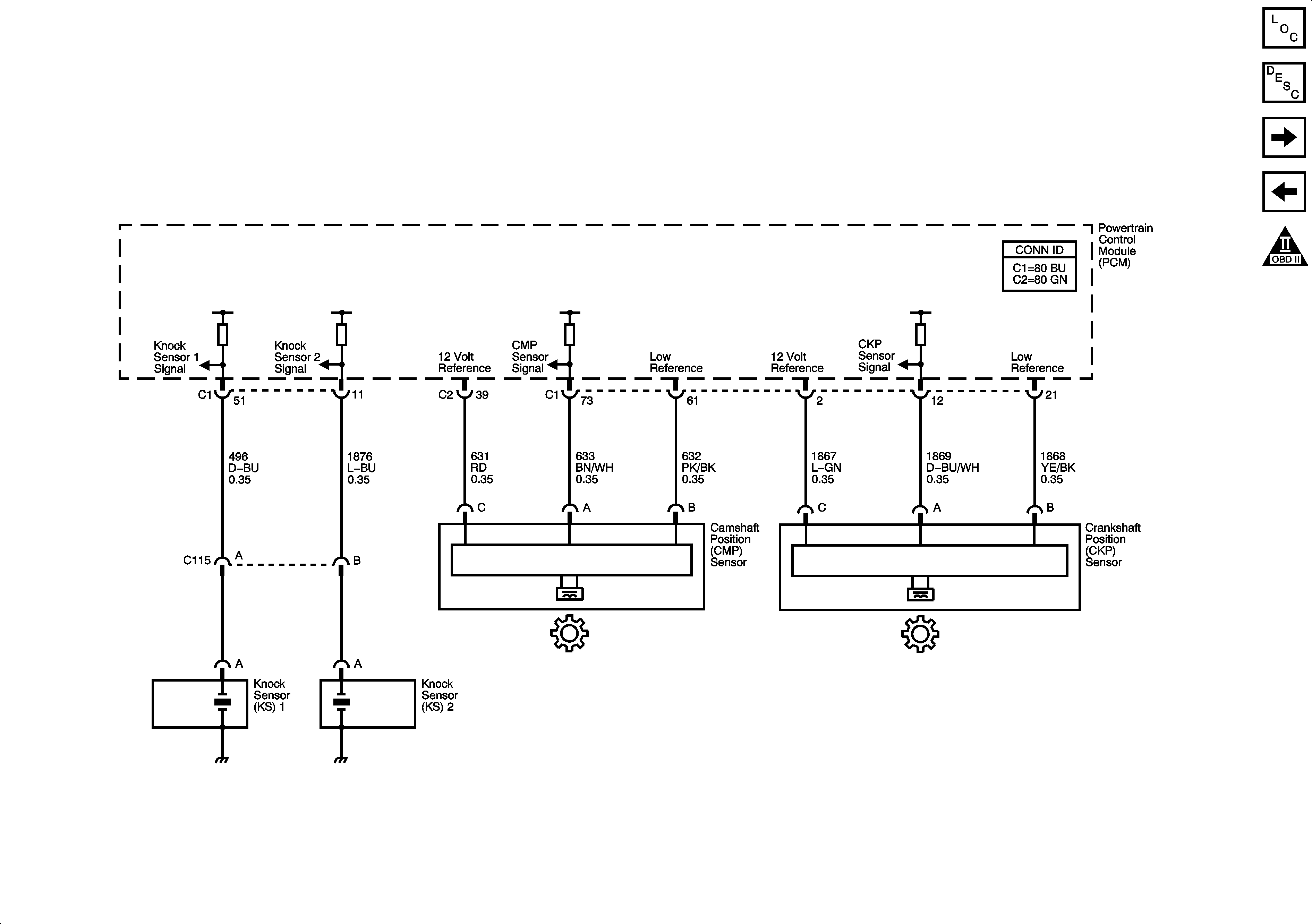
Figure
9:
Fuel Controls - Fuel Pump Controls and Fuel Injectors
Master Electrical Component List
Powertrain Control Module Description
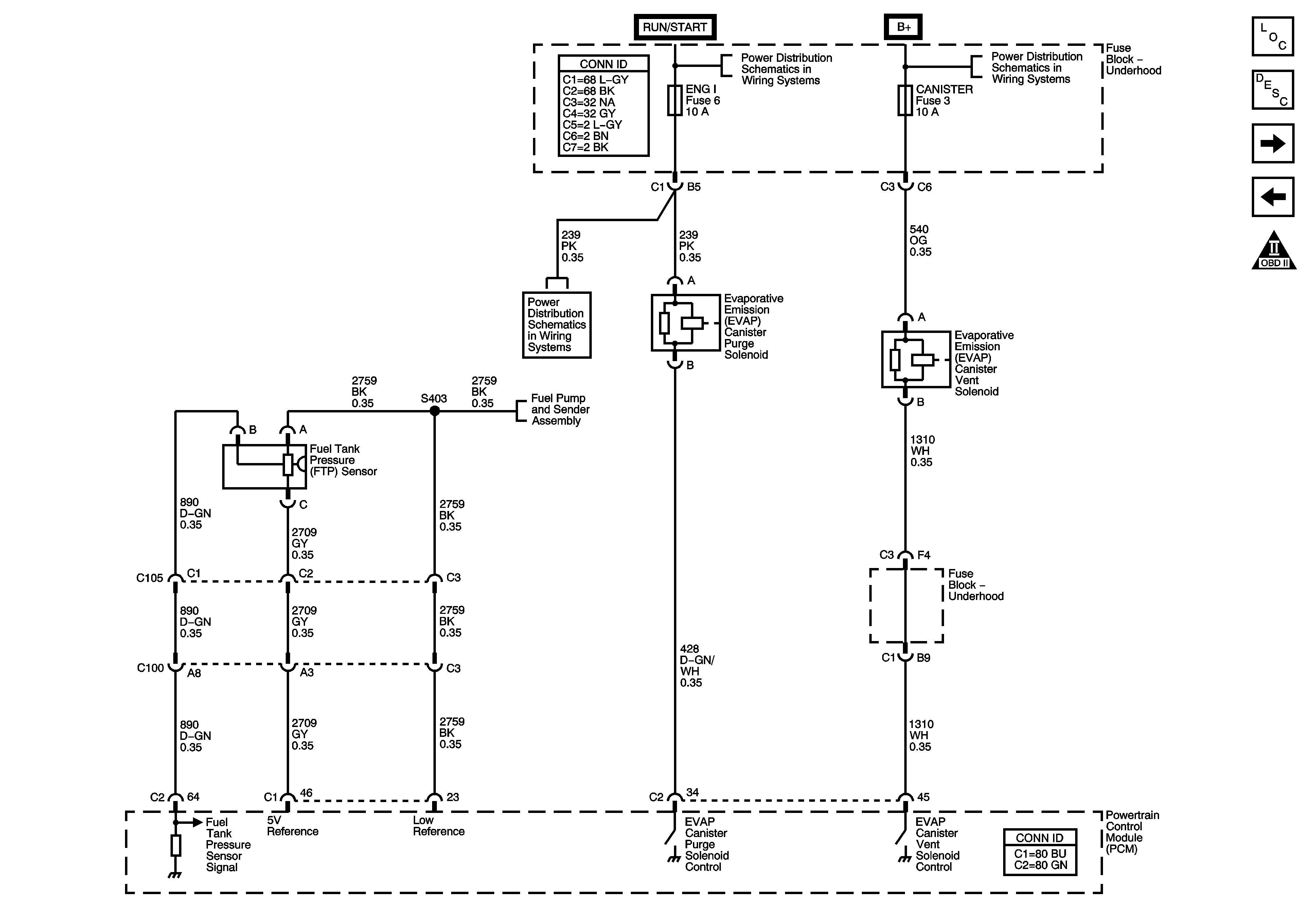
Fuel Controls - EVAP Controls
Ignition Controls - Sensors
OBD II Symbol Description Notice
Power, Ground, Serial Data and MIL
B+ Bus - Fuse Block Underhood
COILS, CANISTER, IPC/DIC, FLASH, TBC1 and PCMB Fuses
G100, G102
TAC, INJA and INJB Fuses
Fuel Controls - EVAP Controls
Figure
10:
Fuel Controls - EVAP Controls
Master Electrical Component List
Powertrain Control Module Description
Controlled/Monitored Subsystem References
Fuel Controls - Fuel Pump Controls and Fuel Injectors
OBD II Symbol Description Notice
ACCY/RUN and RUN/START Bus Bar
B+ Bus - Fuse Block Underhood
PCM I, SIR, 02A, 02B AND ENG I Fuses
Fuel Controls - Fuel Pump Controls and Fuel Injectors
Figure
11:
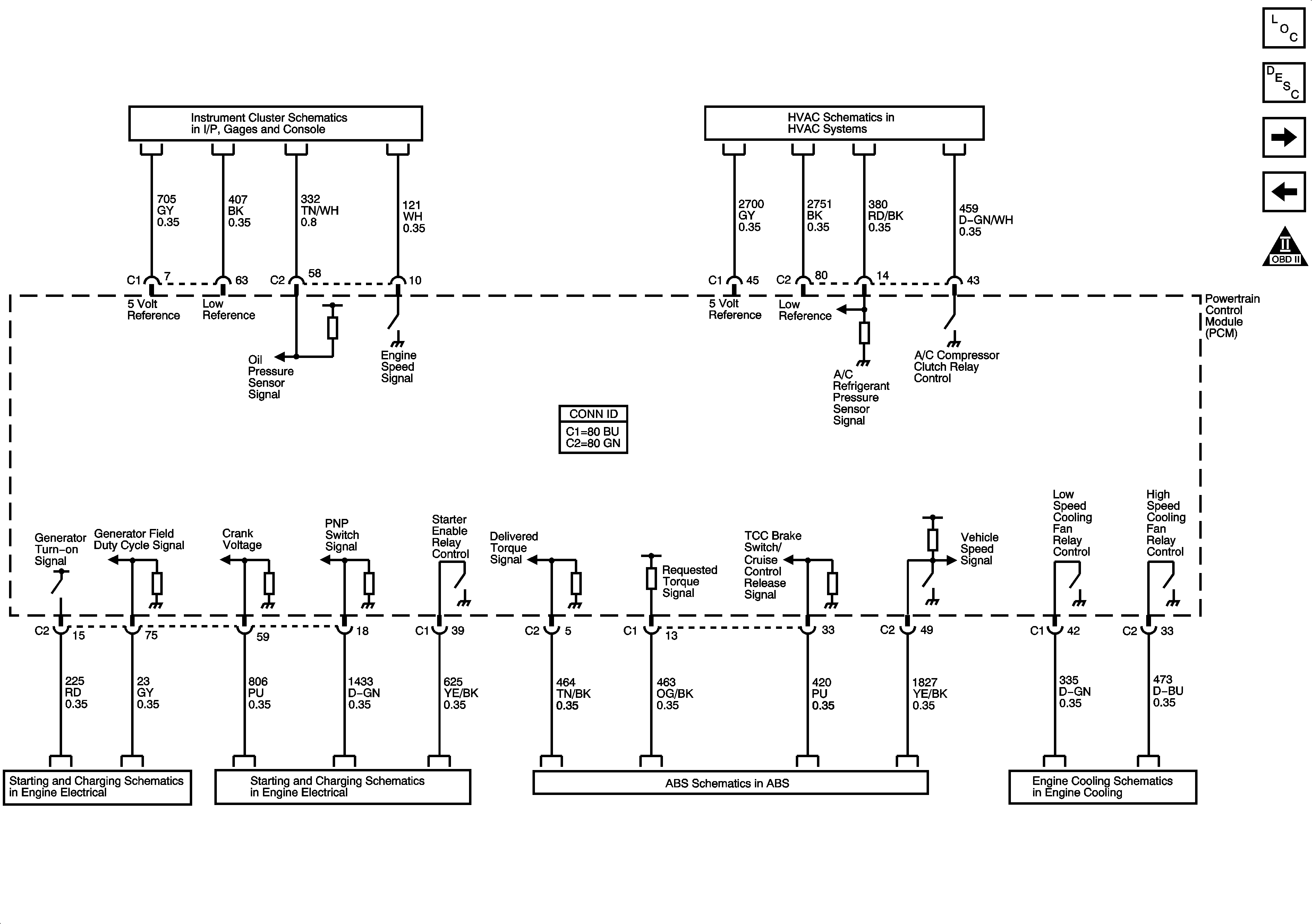
Controlled/Monitored Subsystem References
Master Electrical Component List
Powertrain Control Module Description
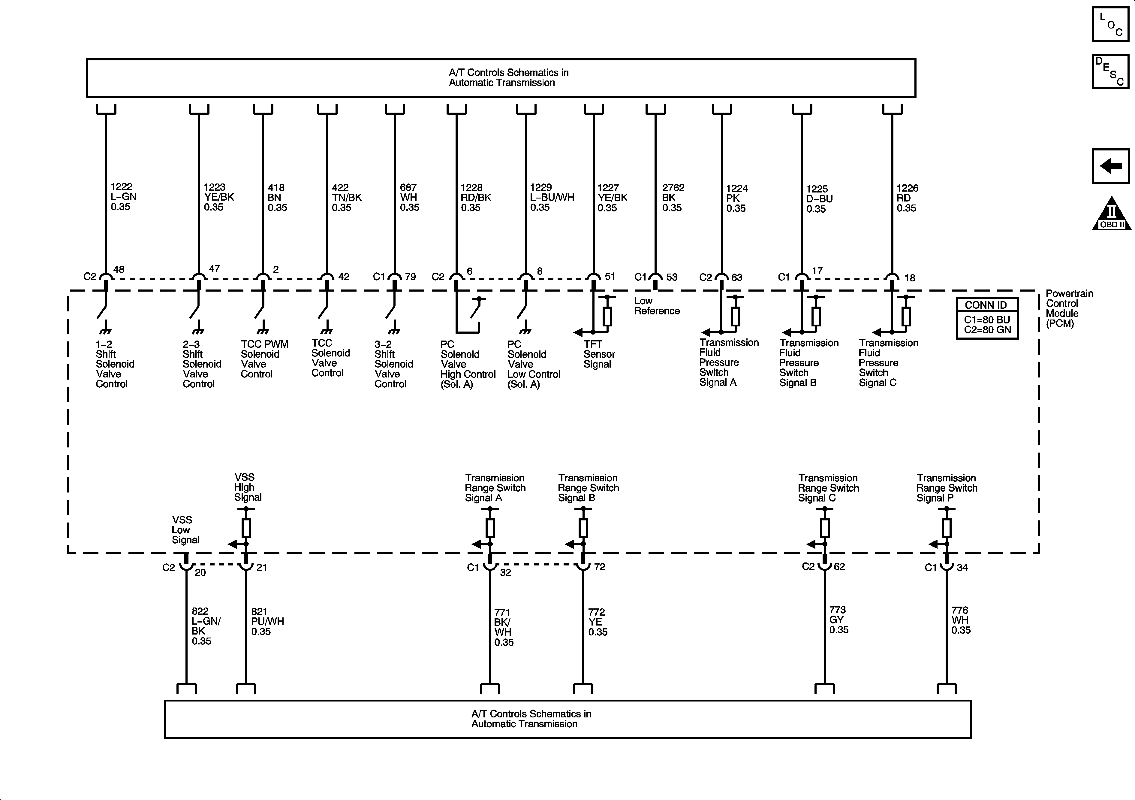
Transmission Control References - A/T
Fuel Controls - EVAP Controls
OBD II Symbol Description Notice
Gages and Engine Oil Pressure (EOP) Sensor
A/C Compressor Control
Engine Electrical - Charging System
Engine Electrical - Starting System
Power, Ground and Electronic Brake Control Module
Engine Cooling
Figure
12:
Transmission Control Reference - A/T
Master Electrical Component List
Powertrain Control Module Description
Controlled/Monitored Subsystem References
OBD II Symbol Description Notice
Power and Internal Transmission Valve Switches
Park/Neutral Position (PNP) Switch and VSS Sensor