For 1990-2009 cars only
Knock Sensor Replacement Left
Removal Procedure
- Raise the vehicle. Refer to Lifting and Jacking the Vehicle in General Information.
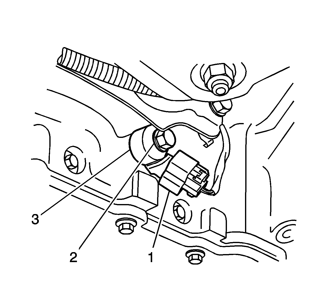
- Remove the electrical connector (1) for the knock sensor (3).
- Remove the retaining bolt (2) for the knock sensor (3).
- Remove the knock sensor (3).

Installation Procedure
- Position the knock sensor (3) on the engine block.
- Install the retaining bolt (2) for the knock sensor (3).
- Reconnect the electrical connector (1).
- Lower the vehicle.

Notice: Refer to Fastener Notice in the Preface section.
Tighten
Tighten the knock sensor retaining bolt to 20 N·m
(15 lb ft).
Knock Sensor Replacement Right
Removal Procedure
- Remove the right front tire and wheel assembly. Refer to Tire and Wheel Removal and Installation in Tires and Wheels.
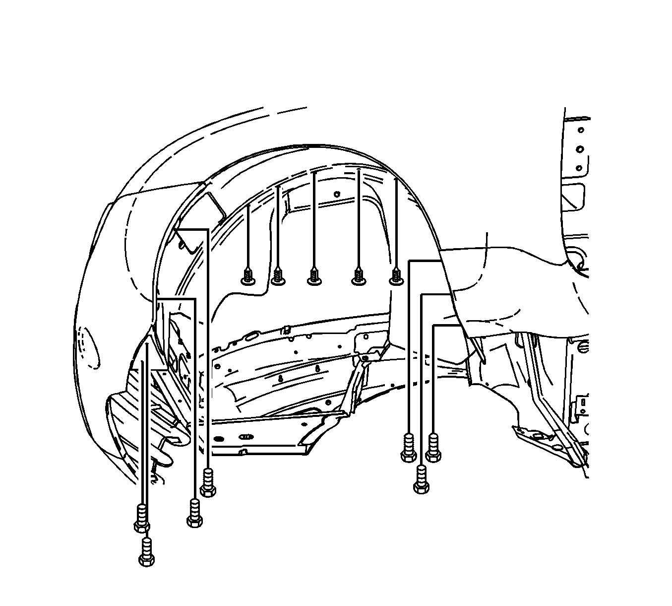
- Remove the inner wheel well. Refer to Front Wheelhouse Liner Replacement in Body Front End.
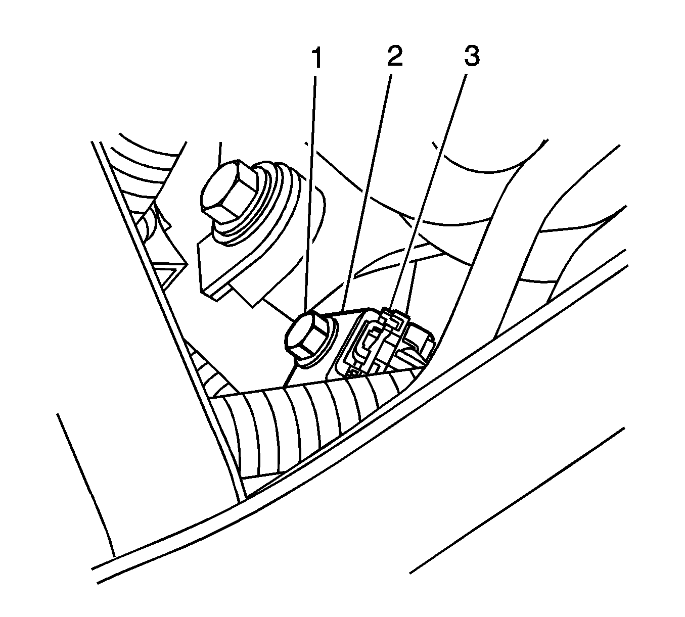
- Remove the retaining bolt for the knock sensor (KS) (1).
- Remove the KS (2).
- Remove the electrical connector for the KS (3).


Installation Procedure
- Reconnect the KS electrical connector.
- Position the KS on the engine block.
- Install the retaining bolt for the KS.
- Install the right wheelhouse liner. Refer to Front Wheelhouse Liner Replacement in Body Front End.
- Install the right front tire and wheel assembly. Refer to Tire and Wheel Removal and Installation in Tires and Wheels.

Notice: Refer to Fastener Notice in the Preface section.
Tighten
Tighten the KS retaining bolt to 20 N·m
(15 lb ft).

