Removal Procedure
Important: The following service procedure also includes the servicing of the fuel rail crossover pipe.
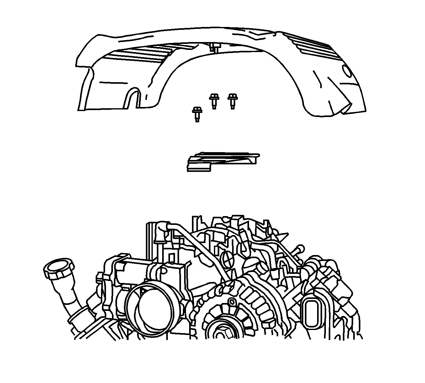
- Remove the engine sight shield. Refer to Upper Intake Manifold Sight Shield Replacement in Engine Mechanical - 6.0L.
- Using compressed filter air, remove the any dirt or debris from the area around the fuel injectors.
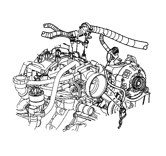
- Remove the upper engine harness from the intake manifold.
- Relieve the pressure in the fuel system. Refer to Fuel Pressure Relief .
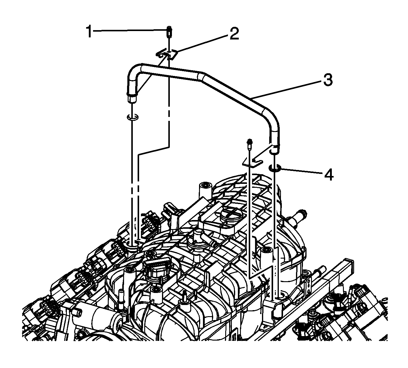
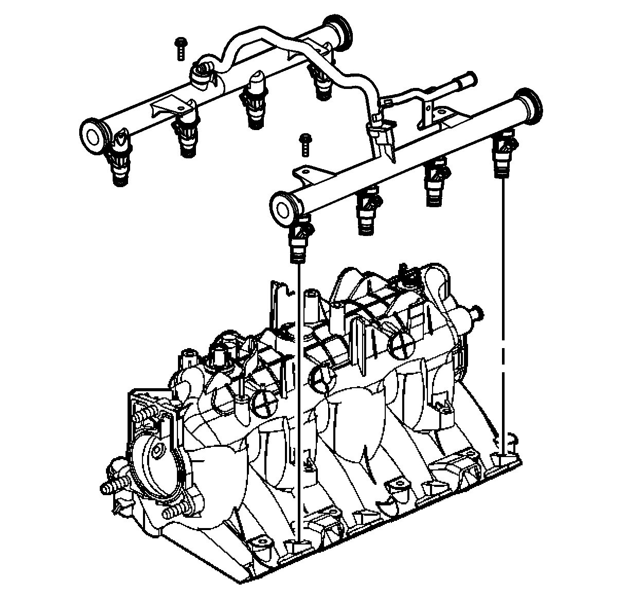
- Remove the fuel rail crossover pipe (3), O-rings (4), retaining screws (1) and tabs (2), if needed.
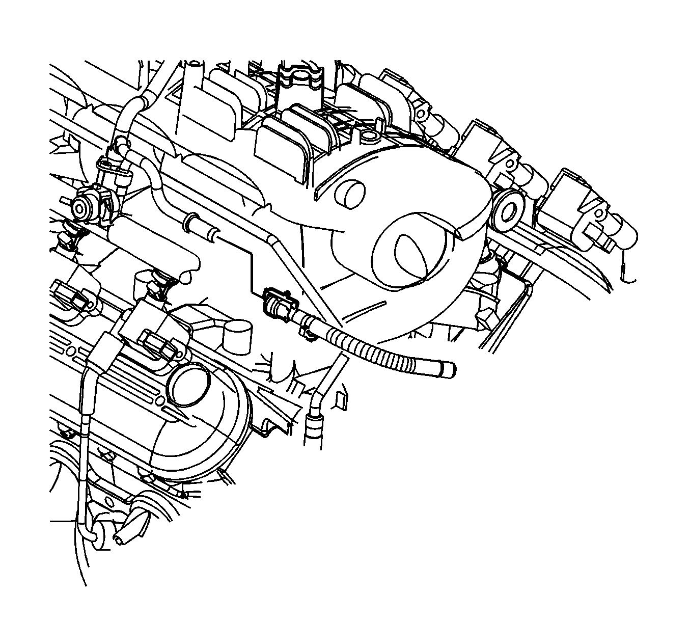
- Disconnect the evaporative emission (EVAP) purge valve harness connector.
- Reposition the engine wiring harness to the side.
- Mark the electrical connector to the fuel injector for the proper installation.
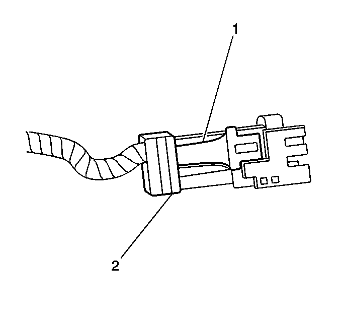
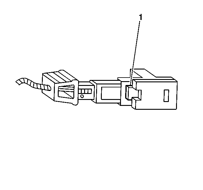
- Pull the top portion (2) of the connector forward. DO NOT pull the top portion the connector past the top of the white portion (1).
- Push the lower side of the connector (1) to release the fuel injector.
- Push the tab (1) on the lower side of the connector in order to release the connector from the injector.
- Disconnect the fuel feed line.
- Remove the fuel rail mounting bolts.
- Remove the fuel rail.
- Remove the fuel injectors. Refer to Fuel Injector Replacement .
Notice:
• Remove the fuel rail assembly carefully in order to prevent damage
to the injector electrical connector terminals and the injector spray tips.
Support the fuel rail after the fuel rail is removed in order to avoid damaging
the fuel rail components. • Cap the fittings and plug the holes when servicing the fuel system
in order to prevent dirt and other contaminants from entering open pipes and
passages.
Installation Procedure
- Install the fuel rail in the intake manifold.
- Apply a 5 mm (0.20 in) band of GM P/N 12345382 (Canadian P/N 10953489) threadlock, or equivalent, to the threads of the fuel rail bolts.
- Install the fuel rail mounting bolts.
- Install the fuel rail crossover pipe (3), O-rings (4), retaining bolts (1) and tabs (2), if removed.
- Connect the fuel feed pipe.
- Reconnect the electrical connectors for the fuel injectors. A click will be felt or heard when the electrical connector is properly connected.
- Position the engine wiring harness on the intake manifold.
- Connect the EVAP purge valve and harness.
- Install the engine sight shield mounting bracket.
- Connect the negative battery cable. Refer to Battery Negative Cable Disconnection and Connection in Engine Electrical.
- Use the following procedure to inspect for fuel leaks:
- Install the engine sight shield. Refer to Upper Intake Manifold Sight Shield Replacement in Engine Mechanical - 6.0L.

Notice: Refer to Fastener Notice in the Preface section.
Tighten
Tighten the fuel rail mounting bolts to 10 N·m
(89 lb in).

Tighten
Tighten the fuel rail crossover pipe retaining screws
to 3.8 N·m (34 lb in).

Important: Ensure that the fuel injector electrical connector are connected to the correct fuel injector. It may also be necessary to rotate the fuel injector the proper alignment between the fuel injector and the electrical connector.

Tighten
Tighten the engine sight shield mounting bolts to
5.5 N·m (49 lb in).
| 11.1. | Turn the ignition to the ON position for 2 seconds. |
| 11.2. | Turn the ignition OFF for 10 seconds. |
| 11.3. | Turn the ignition to the ON position once again. |
| 11.4. | Inspect for any fuel leaks. |

