Tools Required
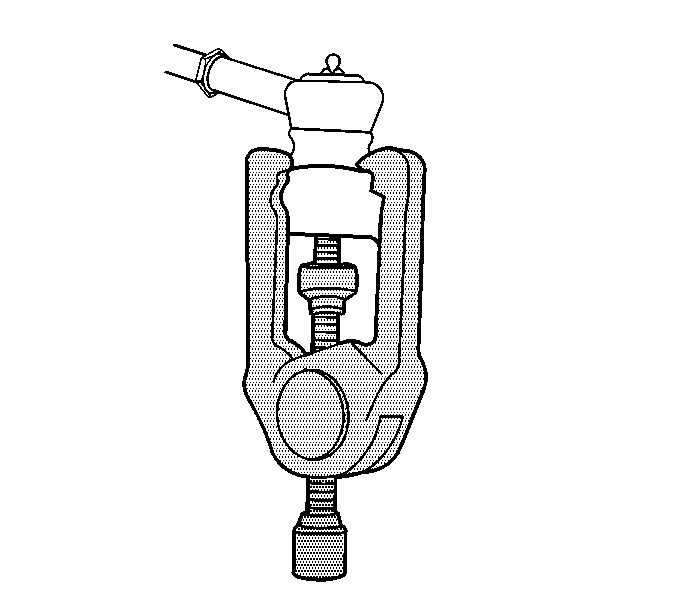
| • | J 24319-B Steering Linkage and Tie Rod Puller |
| • | J 43631 Ball Joint Remover |
Removal Procedure
- Raise and support the vehicle. Refer to Lifting and Jacking the Vehicle .
- Remove the tire and wheel. Refer to Tire and Wheel Removal and Installation .
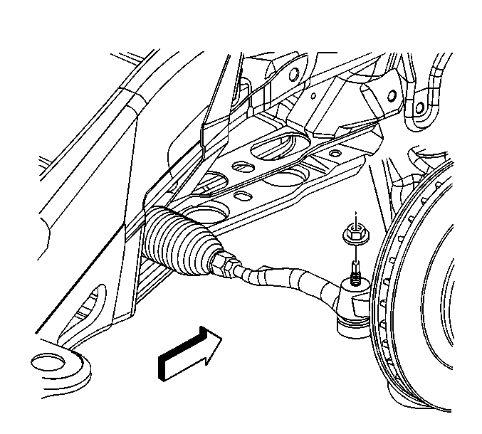
- Remove the outer tie rod retaining nut.
- Disconnect the outer tie rod from the steering knuckle using the J 24319-B .
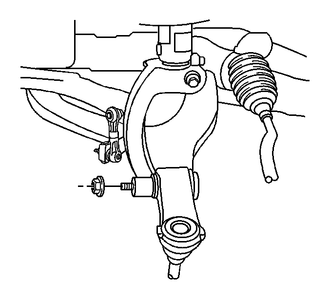
- Remove the stabilizer shaft link lower retaining nut.
- Disconnect the stabilizer shaft link and washer from the lower control arm.
- Remove the shock module yoke lower mounting nut.
- Disconnect the shock module yoke from the lower control arm using the J 24319-B .
- Remove the lower ball joint retaining nut.
- Disconnect the lower ball joint from steering knuckle using the J 43631 .
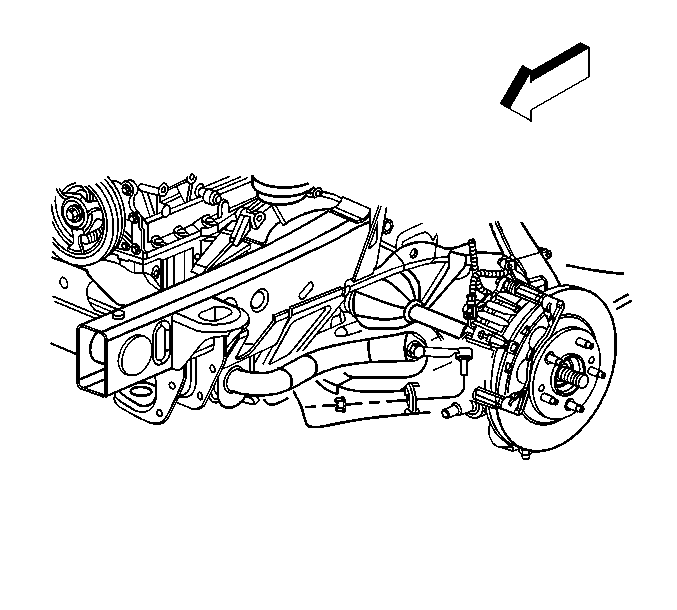
- Remove the lower control arm to lower control arm bracket mounting nuts.
- Remove the lower control arm to lower control arm bracket mounting bolts.
- Pivot the lower control arm outward and downward in order to disconnect the lower control arm from the lower control arm bracket.
- Remove the lower control arm from the vehicle.
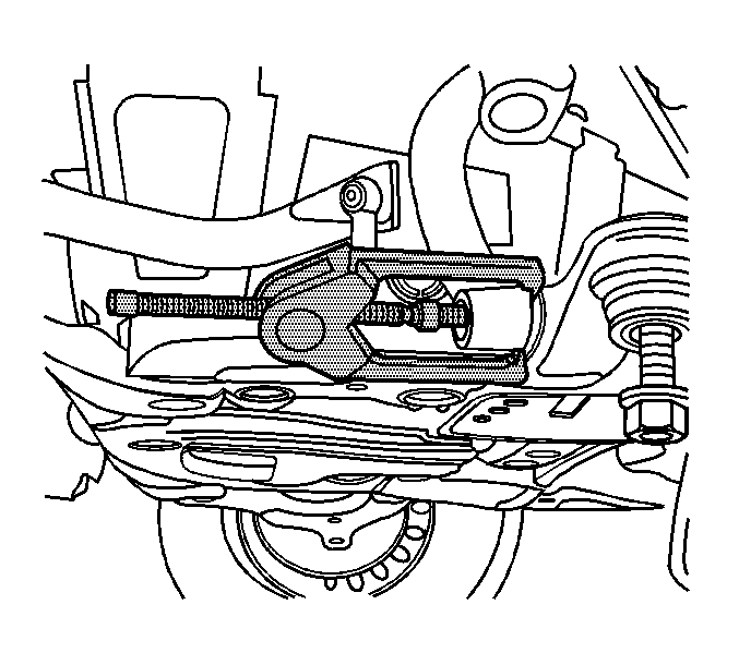
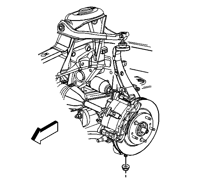
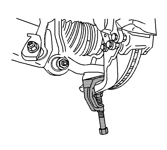
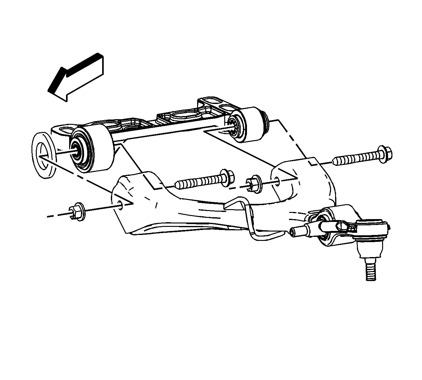
Important: Note the direction the bolts are removed for installation.
Important: Take care not to disengage the axle shaft from the transmission (4WD only).
Important: Ensure that the spacer stays in position on the front control arm bracket front bushing.
Installation Procedure
- Position the lower control arm ball joint stud to the steering knuckle.
- Pivot the lower control arm outward and upward in order to connect the lower control arm to the lower control arm bracket.
- Install the lower control arm to lower control arm bracket mounting bolts.
- Install the lower control arm to lower control arm bracket mounting nuts.
- Connect the shock module yoke to the lower control arm.
- Install the shock module yoke lower mounting nut.
- Install the lower ball joint retaining nut.
- Install the stabilizer shaft link and washer to the lower control arm.
- Install the stabilizer shaft link retaining nut.
- Install the outer tie rod to the steering knuckle.
- Install the outer tie rod retaining nut.
- Install the tire and wheel. Refer to Tire and Wheel Removal and Installation .
- Lower the vehicle.
- Inspect the front wheel alignment. Refer to Wheel Alignment Specifications .
Important: Take care not to disengage the axle shaft from the transmission.

Important: Ensure that the spacer stays in position on the front control arm bracket front bushing.
Notice: Refer to Fastener Notice in the Preface section.
Important: Ensure that the lower control arm is parallel to the lower control arm bracket during the installation and tightening of the lower control arm mounting bolts and nuts. This will ensure correct alignment of the lower control arm bushings.
Tighten
Tighten the nuts to 130 N·m (96 lb ft).

Tighten
Tighten the nut to 110 N·m (81 lb ft).

Tighten
Tighten the nut to 110 N·m (81 lb ft).

Important: There is a washer between the stabilizer shaft link and the lower control arm made of hardened steel and has a felt inner liner. Only replace this washer with an identical washer. Standard washers should not be used.
Tighten
Tighten the nut to 155 N·m (114 lb ft).
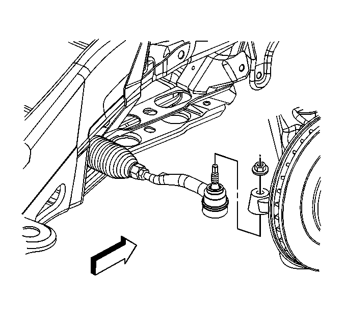
Tighten
Tighten the nut to 45 N·m (33 lb ft).
