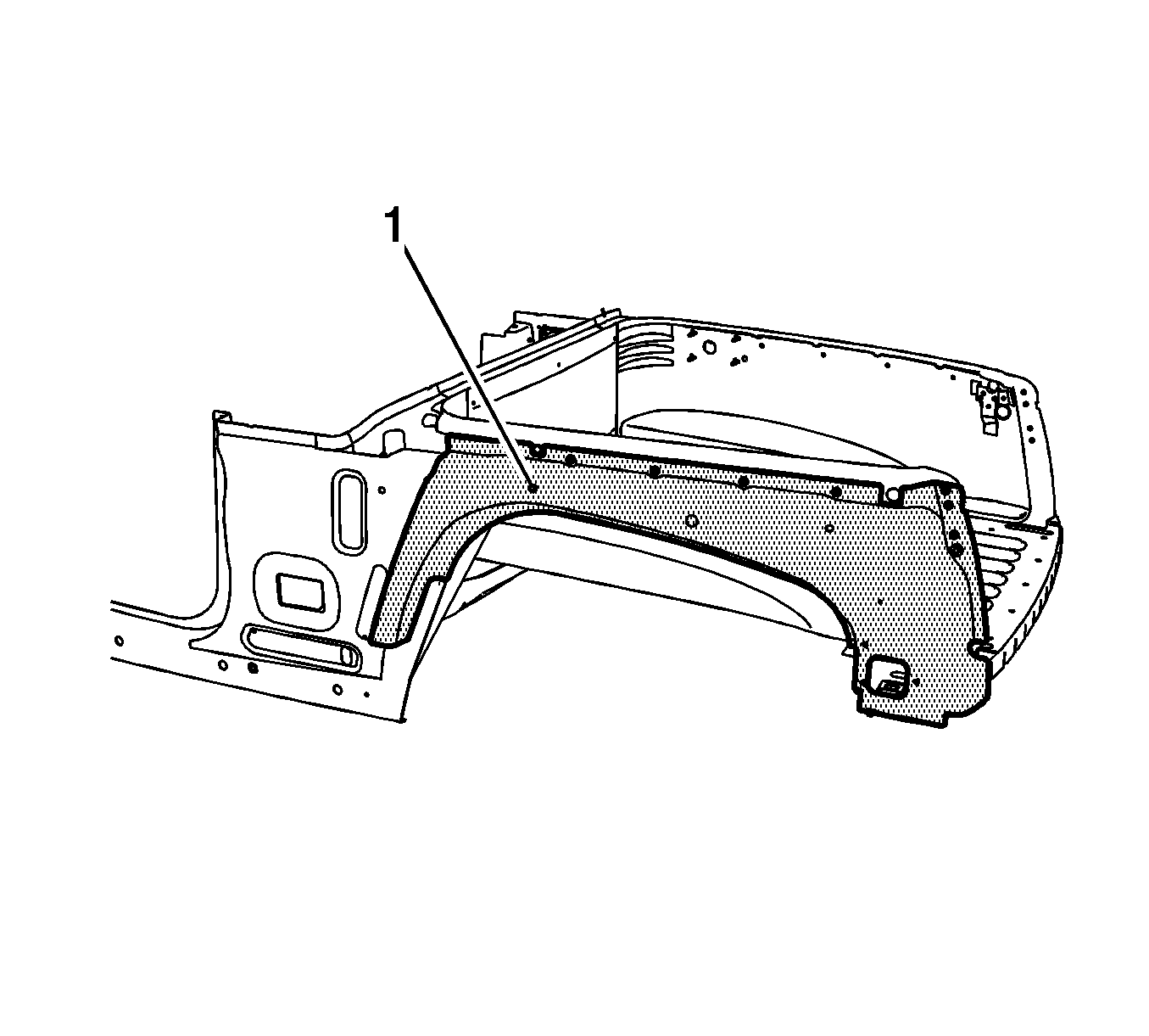
Rear Outer Wheelhouse Replacement Complete
Removal Procedure
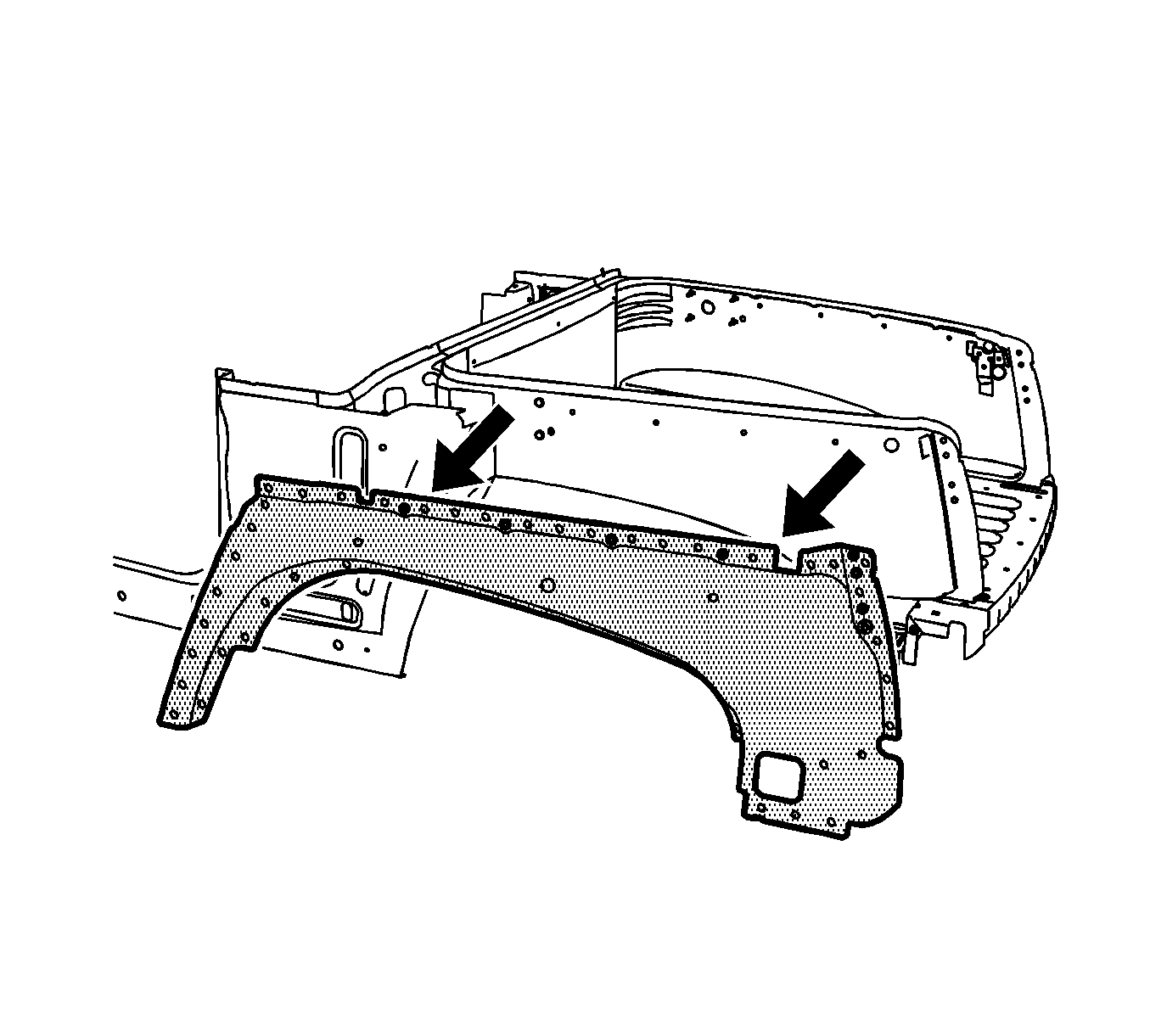
Caution: Refer to Approved Equipment for Collision Repair Caution in the Preface section.
Important: Sectioning procedures have been developed to simplify the replacement of the outer body side panel. If the damage is less severe, use the wheelhouse sectioning procedure when replacing either the rear section of the outer body side panel or the entire panel.
- Disable the SIR system. Refer to SIR Disabling and Enabling in SIR.
- Disconnect the negative battery cable. Refer to Battery Negative Cable Disconnection and Connection in Engine Electrical.
- Remove all related panels and components including the outer quarter panel and the lock pillar gusset. Refer to Quarter Outer Panel Replacement and to Rear Compartment Lock Pillar Gusset Replacement .
- Repair as much of the damage as possible to factory specifications. Refer to Rear Cargo Compartment in Dimensions - Body .
- Note the location and remove the sealers and anti-corrosion materials from the repair area, as necessary. Refer to Anti-Corrosion Treatment and Repair in Paint and Coatings.
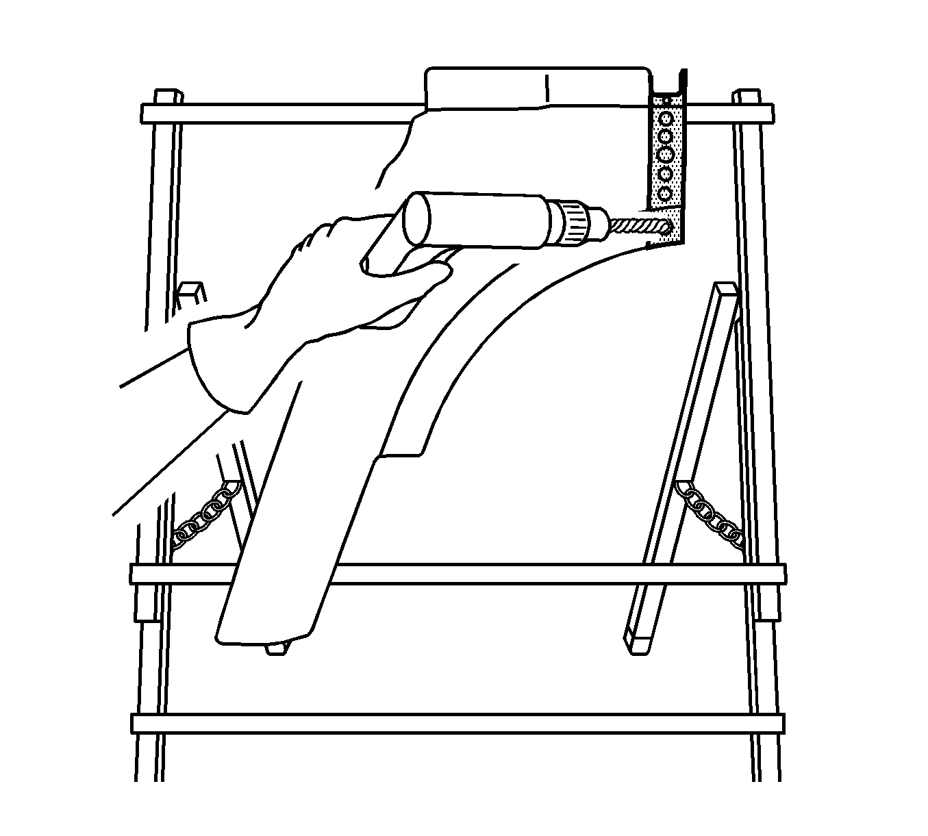
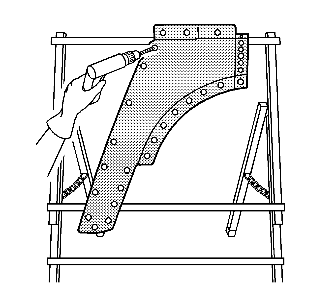
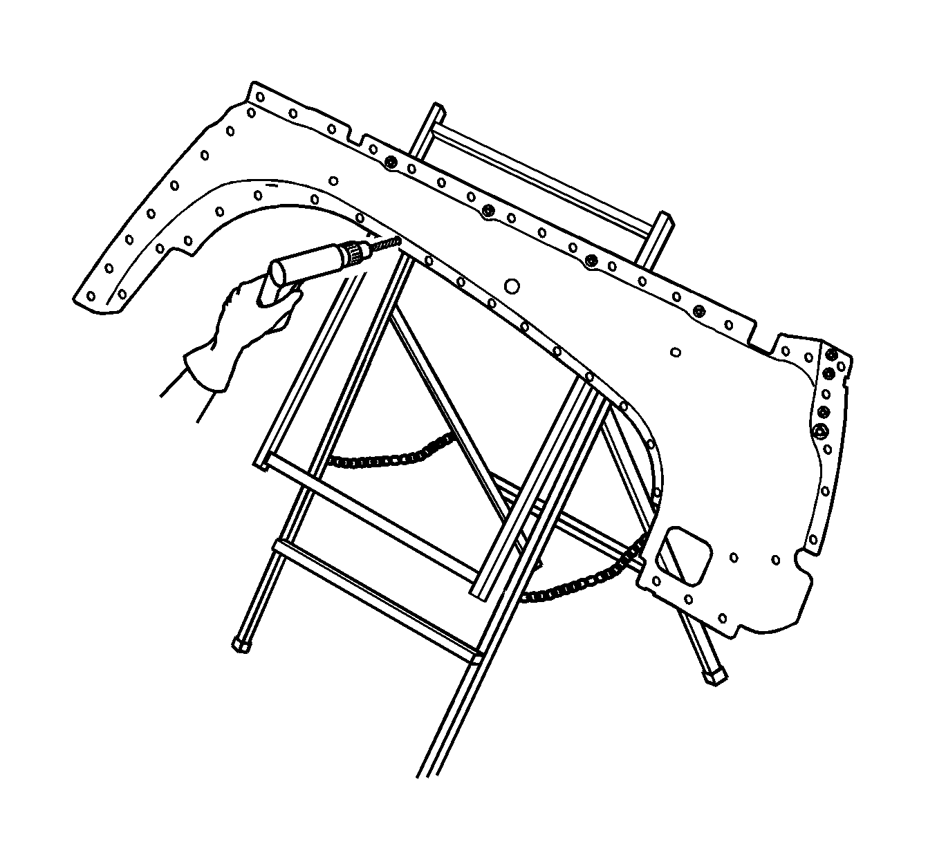
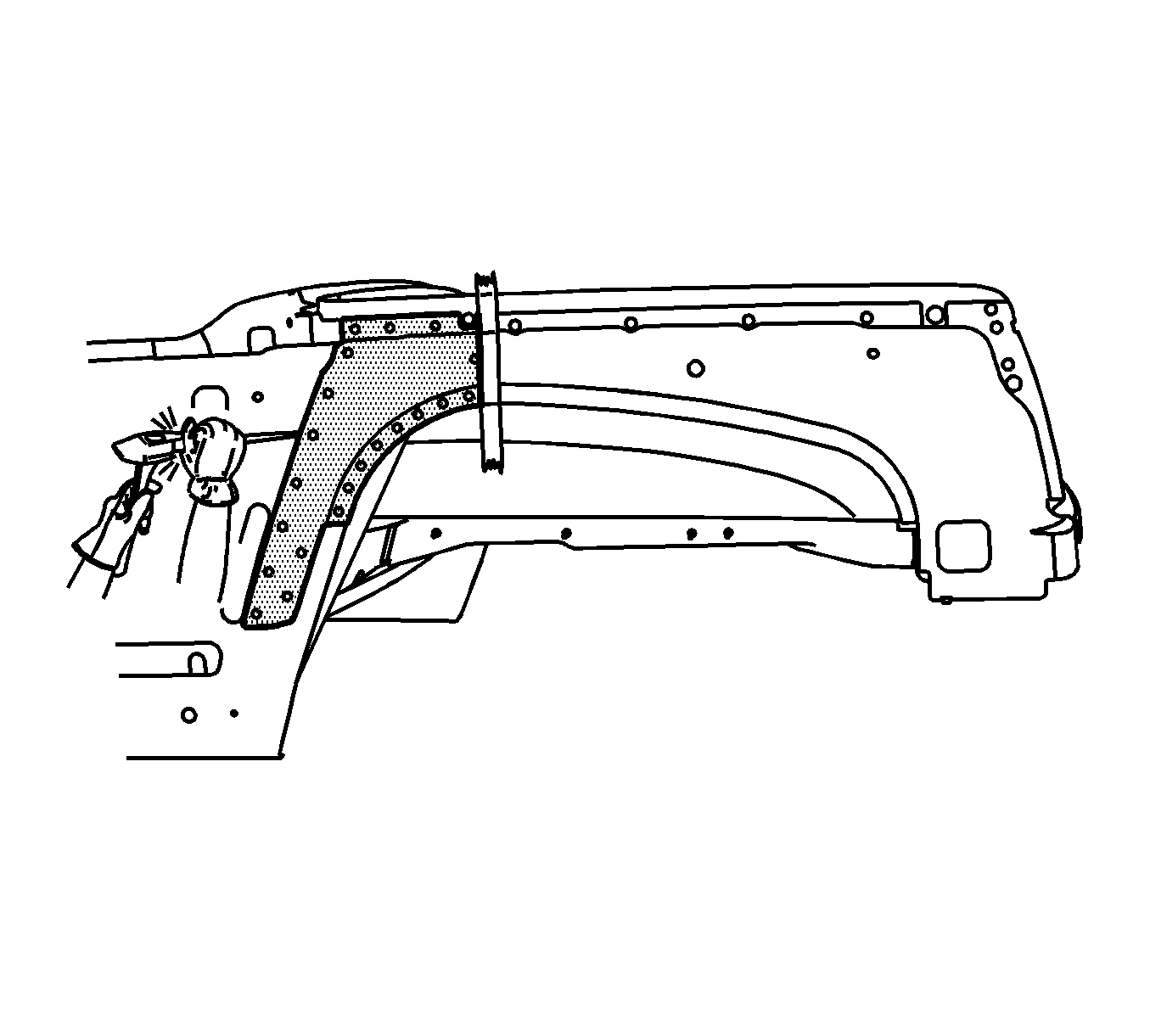
- Locate and drill out all factory welds. Note the number and location of the welds for installation of the outer wheelhouse.
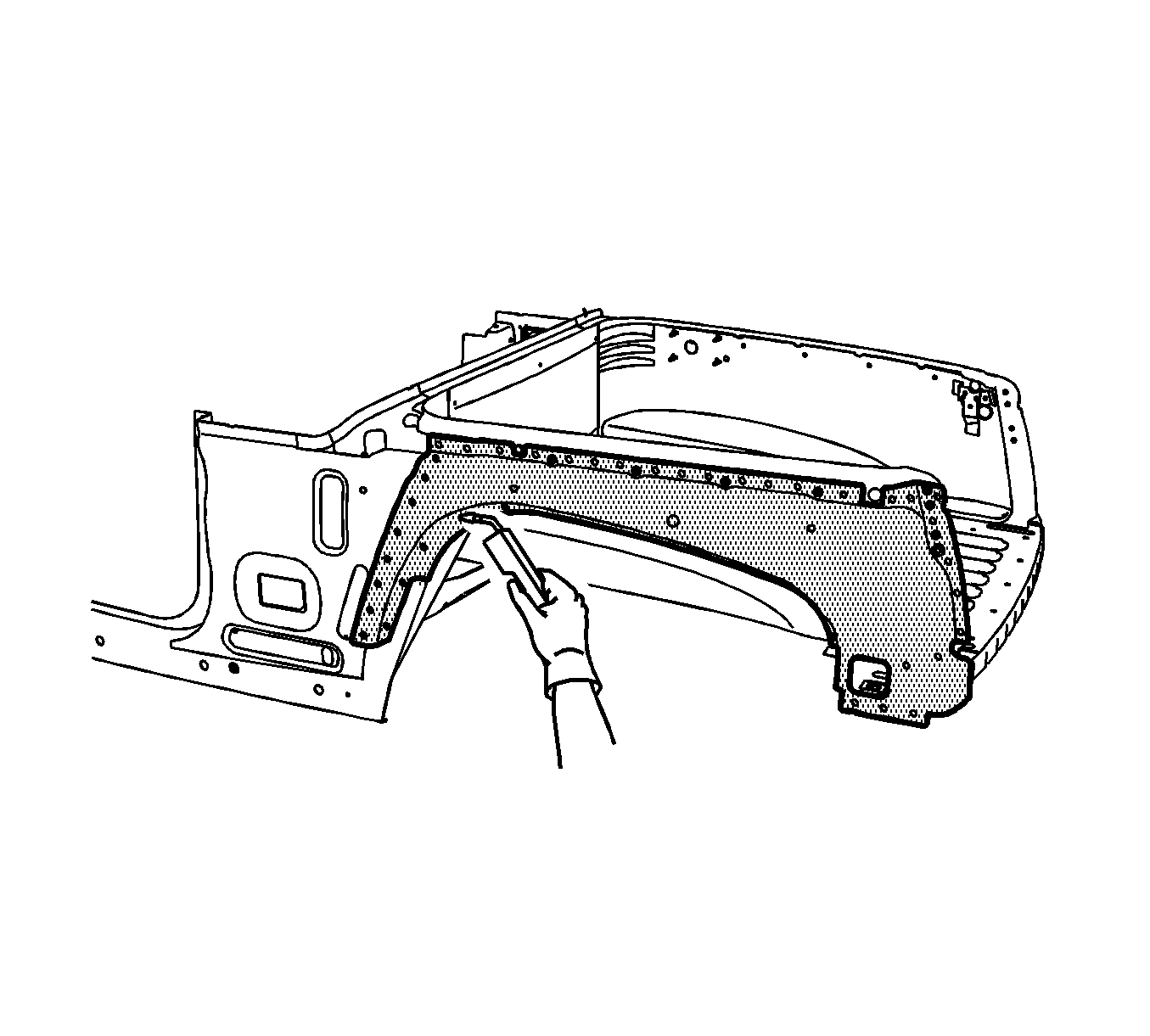
- Verify the existence of structural weld-through adhesive. Refer to Structure Adhesive Identification . If necessary use a chisel to separate the wheelhouse from the box side panel.
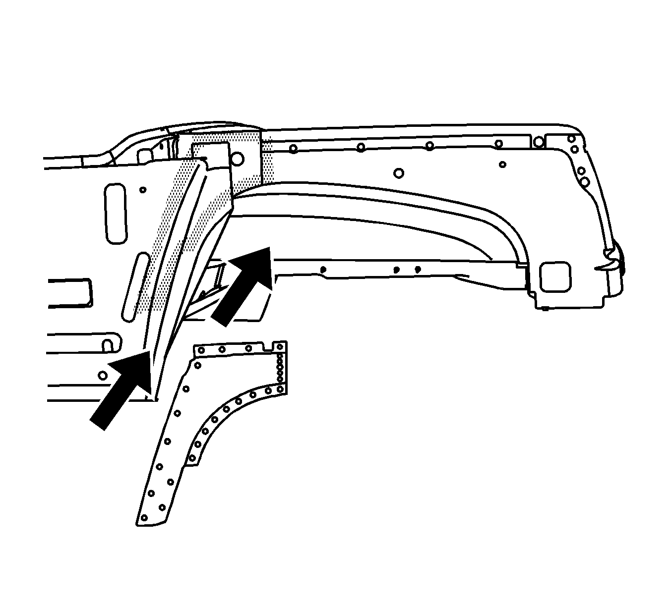
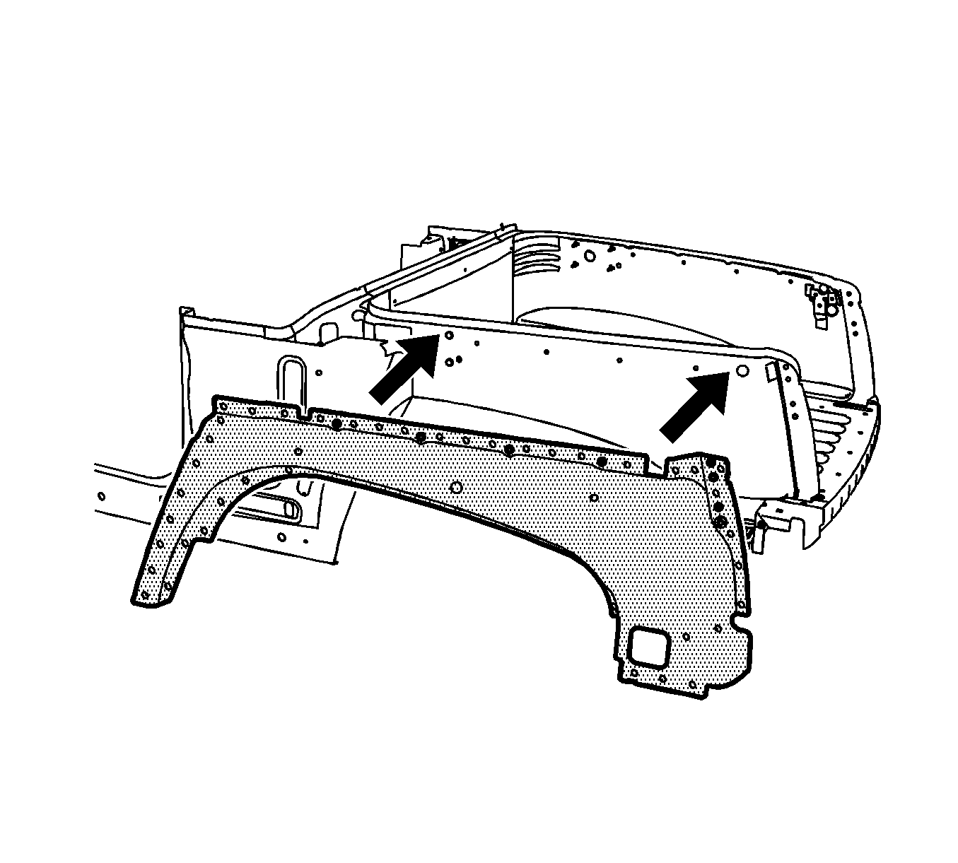
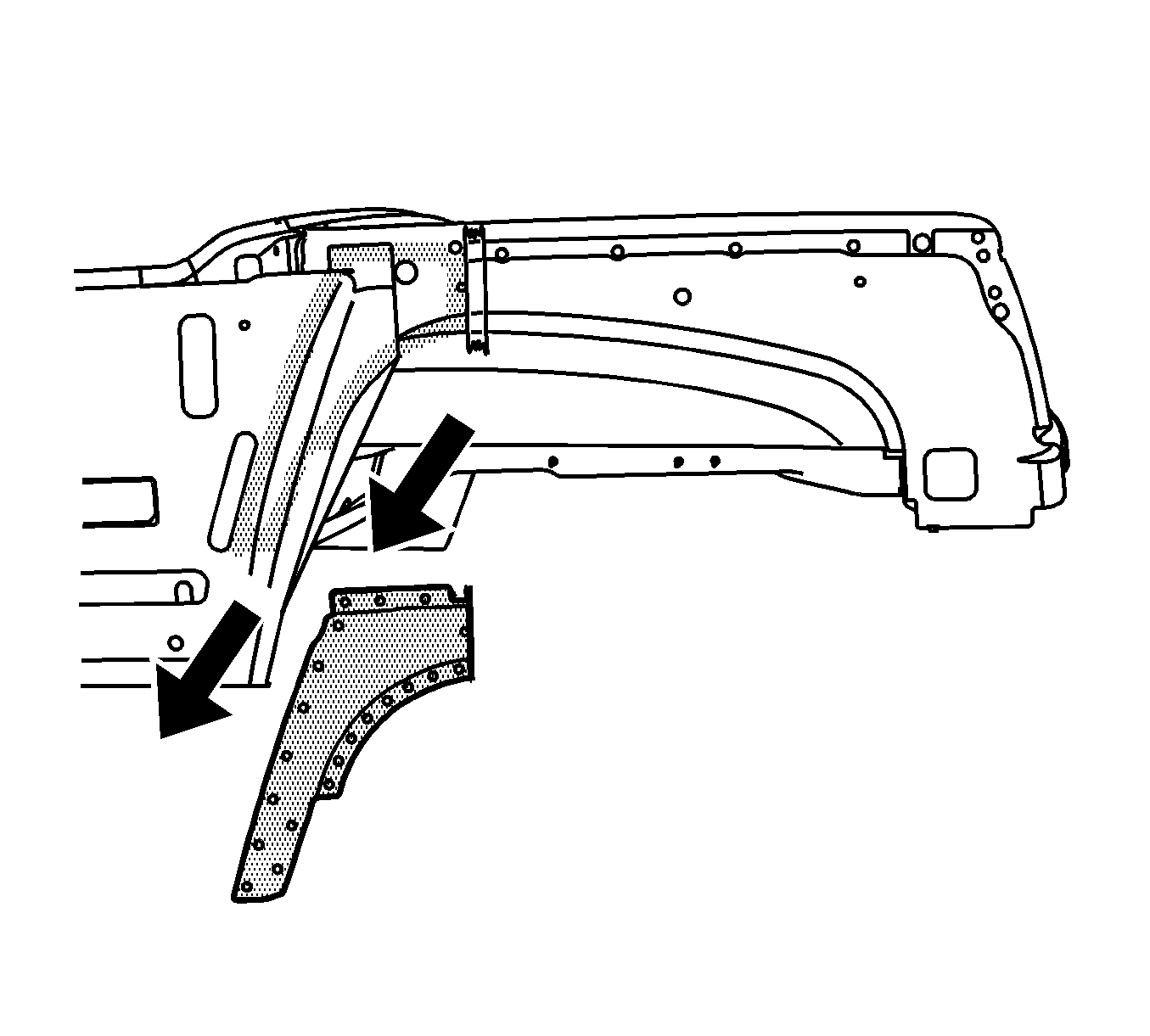
- Remove the damaged wheelhouse panel.
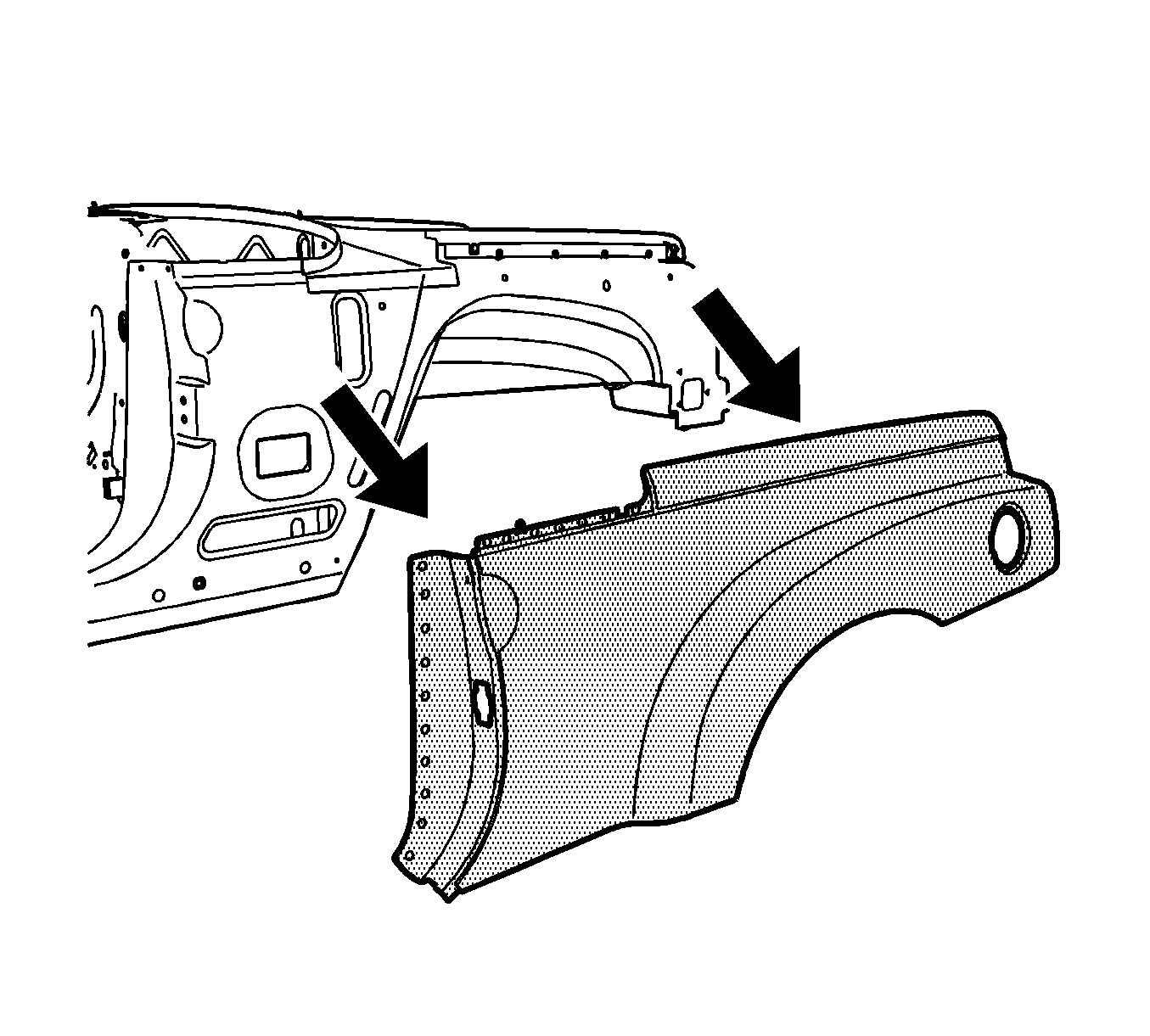
Caution: Refer to Foam Sound Deadeners Caution in the Preface section.
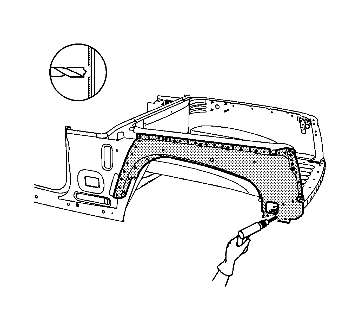
Important: Do NOT damage the inner panels or the reinforcements.
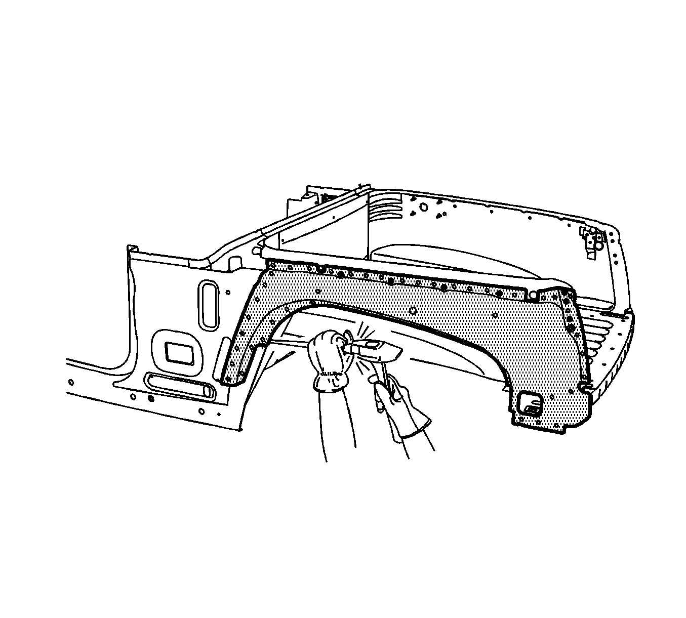

Installation Procedure
- Drill 8 mm (5/16 in) plug weld holes in the service part as necessary in the locations noted on the original panel.
- Replace the structural adhesive with an additional plug weld between existing plug welds where necessary.
- Prepare all mating surfaces as necessary.
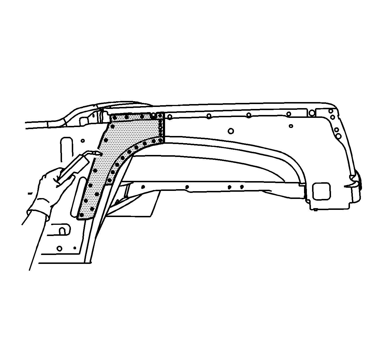
- Apply 3M® Weld-Thru Coating P/N 05916 or equivalent to all mating surfaces.
- Position the wheelhouse panel. Refer to Rear Compartment in Dimensions - Body .
- Plug weld accordingly.
- Install all related panels, including the lock pillar gusset and the outer quarter panel. Refer to Rear Compartment Lock Pillar Gusset Replacement and to Quarter Outer Panel Replacement .
- Clean and prepare all welded surfaces.
- Apply the sealers and the anti-corrosion materials to the repair area, as necessary. Refer to Anti-Corrosion Treatment and Repair in Paint and Coatings.
- Paint the repair area. Refer to Basecoat/Clearcoat Paint Systems in Paint and Coatings.
- Install all related panels and components.
- Connect the negative battery cable. Refer to Battery Negative Cable Disconnection and Connection in Engine Electrical.
- Enable the SIR system. Refer to SIR Disabling and Enabling in SIR.
Rear Outer Wheelhouse Replacement Section
Removal Procedure
- Disable the SIR system. Refer to SIR Disabling and Enabling in SIR.
- Disconnect the negative battery cable. Refer to Battery Negative Cable Disconnection and Connection in Engine Electrical.
- Remove all related panels and components including the outer quarter panel and the lock pillar gusset. Refer to Quarter Outer Panel Replacement and to Rear Compartment Lock Pillar Gusset Replacement .
- Repair as much of the damage as possible to factory specifications. Refer to Rear Cargo Compartment in Dimensions - Body .
- Note the location and remove the sealers and anti-corrosion materials from the repair area, as necessary. Refer to Anti-Corrosion Treatment and Repair in Paint and Coatings.
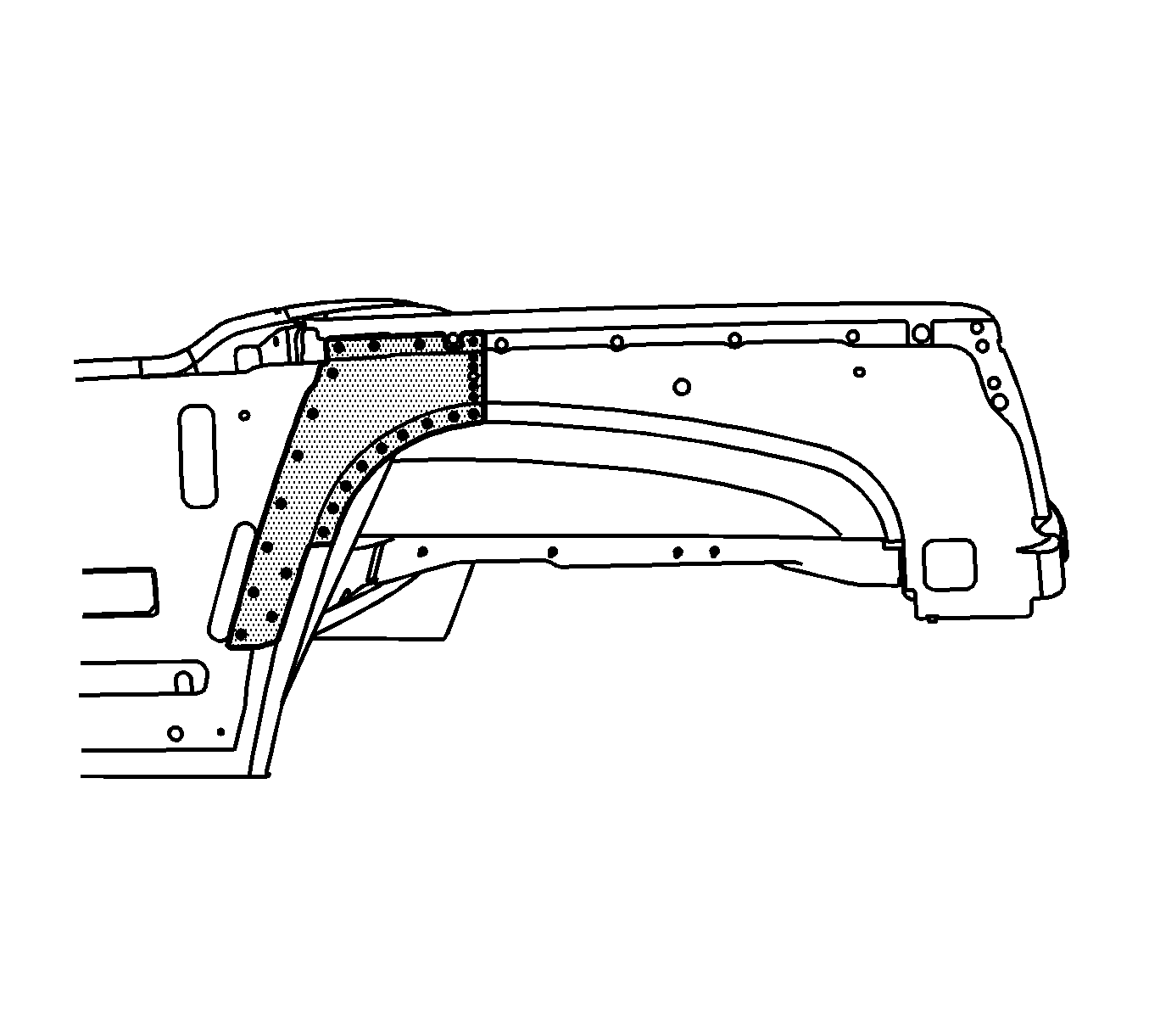
- Locate the 15 mm (5/8 in) hole (1) in the wheelhouse as shown.
- Apply masking tape over the hole and along the entire sectioning location.
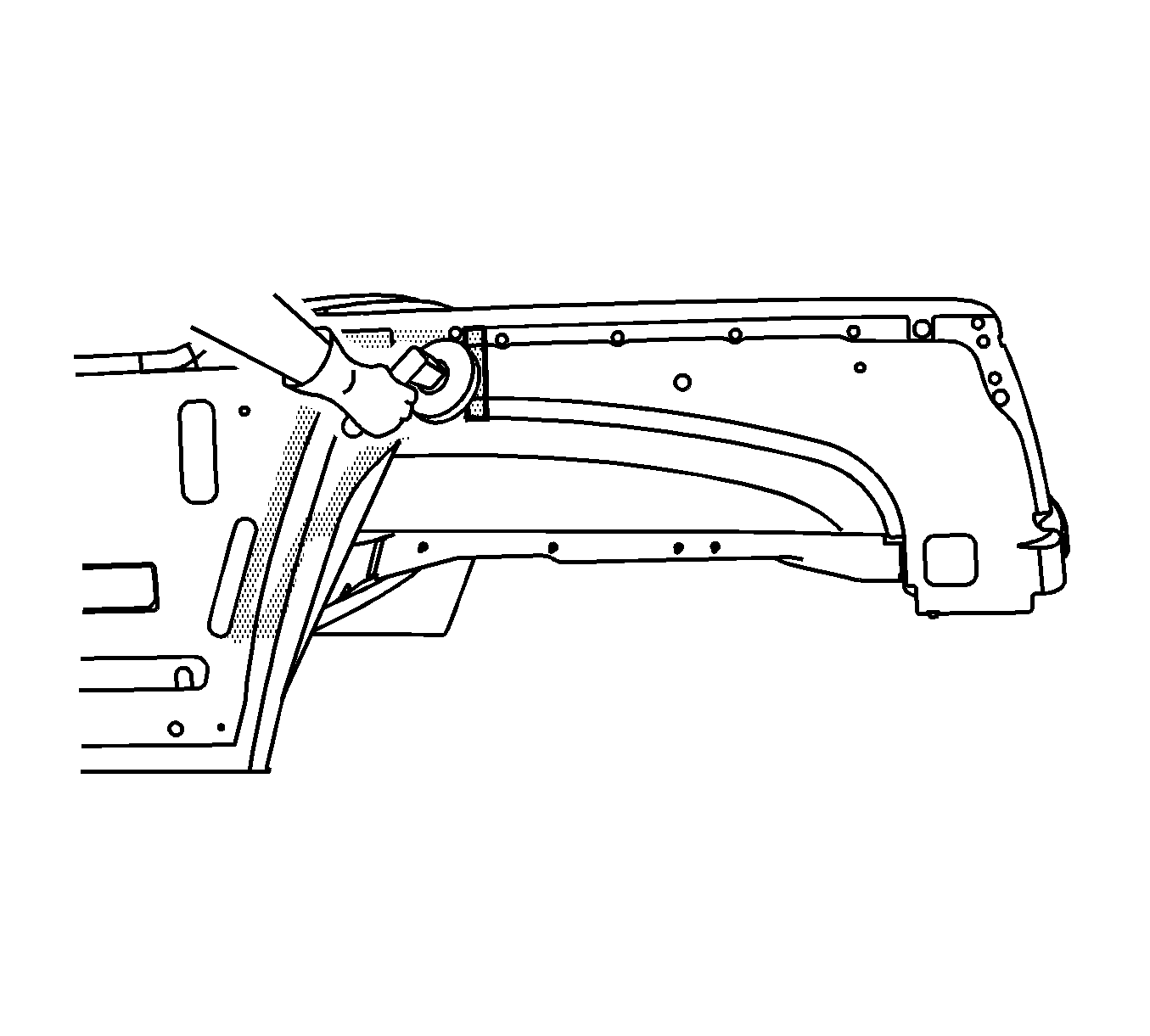
- Cut the wheelhouse along the front edge of the tape using a cut-off wheel or equivalent.
- Locate and drill out all factory welds in front of the sectioning location. Note the number and location of the welds for installation of the front wheelhouse section.
- Verify the existence of structural weld-through adhesive. Refer to Structure Adhesive Identification . If necessary use a chisel to separate the upper fender rail section from the adjacent panels.
- Remove the front wheelhouse section.
- Remove the masking tape and grind to bare metal a 25 mm (1 in) strip at the sectioning location.
Caution: Refer to Approved Equipment for Collision Repair Caution in the Preface section.
Important: Sectioning procedures have been developed to simplify the replacement of the outer body side panel. If the damage is less severe, use the wheelhouse sectioning procedure when replacing either the rear section of the outer body side panel or the entire panel.
Caution: Refer to Foam Sound Deadeners Caution in the Preface section.
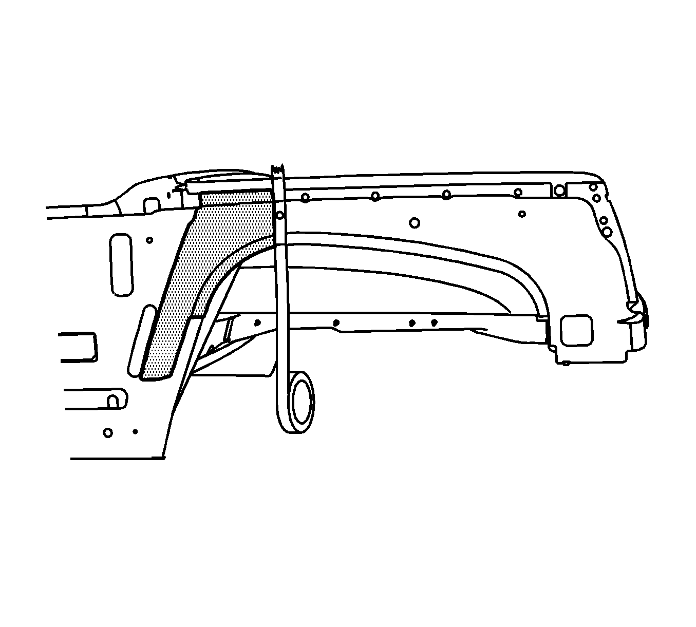
Important: Line up the masking tape vertically along the front edge of the hole as shown.
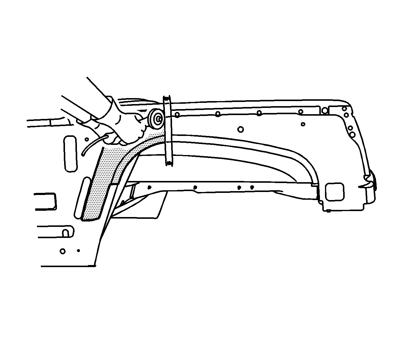
Important: The tape edge facing the front of the vehicle is the proper cut location.
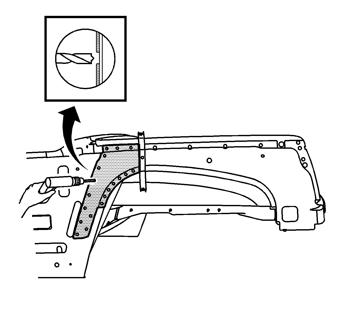
Important: Do NOT damage any inner panels or reinforcements.
Installation Procedure
- On the service wheelhouse panel, locate the 15 mm (5/8 in) hole (1).
- Apply masking tape over the hole and along the entire sectioning location.
- Cut the upper fender rail along the back edge of the tape using a cut-off wheel or equivalent.
- Drill 8 mm (5/16 in) plug weld holes along the sectioning cut. Locate these holes 13 mm (½ in) from the edge and spaced approximately 26 mm (1 in) apart.
- Drill 8 mm (5/16 in) plug weld holes in the service part as necessary in locations noted from the original panel.
- Replace the structural adhesive with an additional plug weld between the existing plug welds, where necessary.
- Prepare all mating surfaces as necessary.
- Apply 3M® Weld-Thru coating P/N 05916 or equivalent to all mating surfaces
- Position the front wheelhouse section. Refer to Rear Cargo Compartment section in Dimensions - Body .
- Plug weld accordingly.
- Clean and prepare all welded surfaces.
- Apply the sealers and anti-corrosion materials to the repair area, as necessary. Refer to Anti-Corrosion Treatment and Repair in Paint and Coatings.
- Paint the repair area. Refer to Basecoat/Clearcoat Paint Systems in Paint and Coatings.
- Install all related panels and components.
- Connect the negative battery cable. Refer to Battery Negative Cable Disconnection and Connection in Engine Electrical.
- Enable the SIR system. Refer to SIR Disabling and Enabling in SIR.
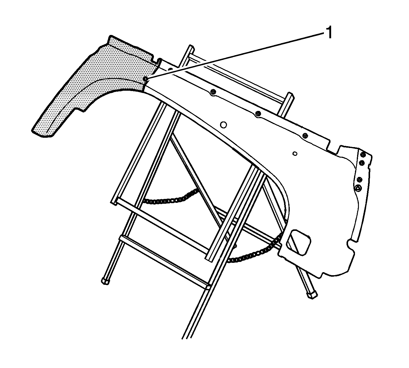
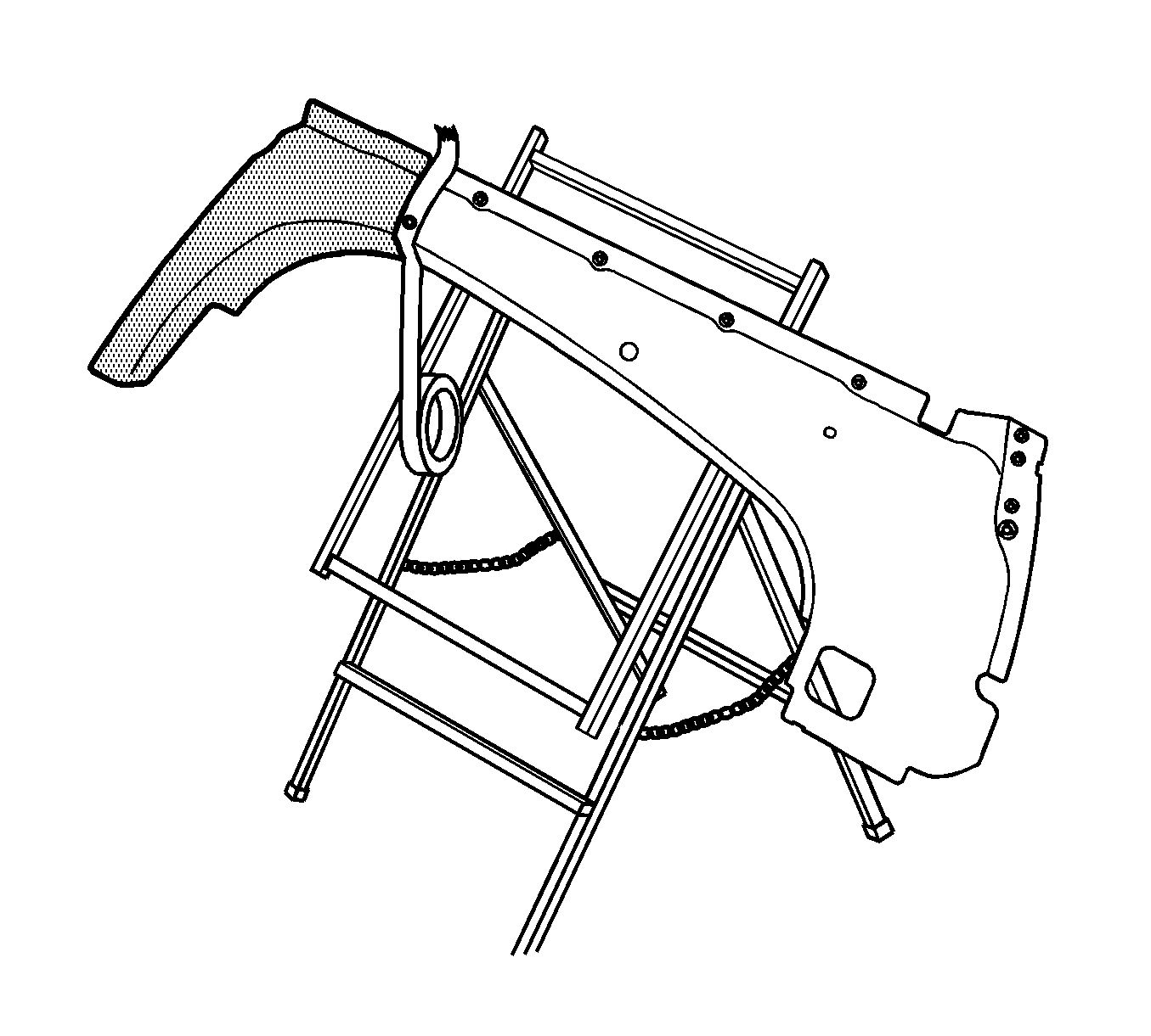
Important: Line up the masking tape vertically along the front edge of the hole as shown.
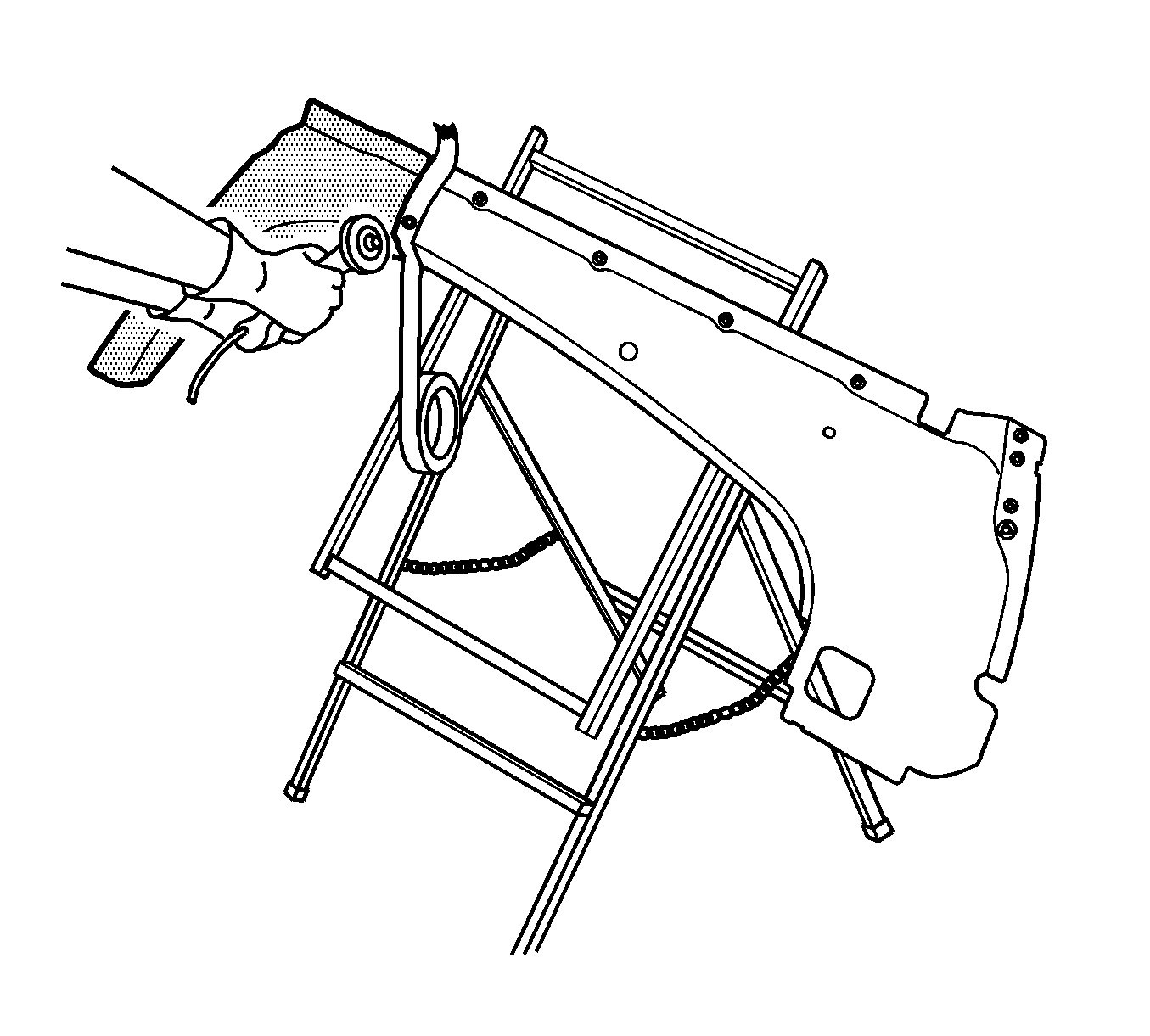
Important: The proper cut location is found along the tape edge facing the rear of the vehicle.
