| Connector 1: | Audio Amplifier C1 (Premium-UQA) |
| Connector 2: | Audio Amplifier C2 (Premium-UQA) |
| Connector 3: | Audio Amplifier C3 (Premium-UQA) |
| Connector 4: | Inflatable Restraint Steering Wheel Module Coil C4 |
| Connector 5: | Noise Compensation Microphone (Premium-UQA) |
| Connector 6: | Radio Antenna Module |
| Connector 7: | Radio C1 |
| Connector 8: | Speaker Assembly - LF Door (Base Radio) |
| Connector 9: | Speaker - LF Door (Premium Radio-UQA) |
| Connector 10: | Speaker - LF Door Midrange (Premium-UQA) |
| Connector 11: | Speaker - LR |
| Connector 12: | Speaker Assembly - RF Door (Base Radio) |
| Connector 13: | Speaker - RF Door (Premium-UQA) |
| Connector 14: | Speaker - RF Door Midrange (Premium-UQA) |
| Connector 15: | Speaker - RR |
| Connector 16: | Steering Wheel Controls - Left |
| Connector 17: | Steering Wheel Controls - Right |
Audio Amplifier C1 (Premium-UQA)
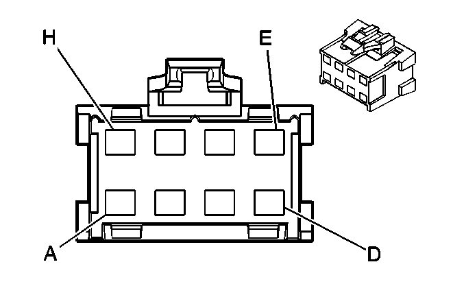
Connector Part Information
|
Pin | Wire Color | Circuit No. | Function |
|---|---|---|---|
A | BK | 1450 | Ground |
B | -- | -- | Not Used |
C | D-GN | 117 | Right Front Speaker Output (-) |
D | TN | 201 | Left Front Speaker Output (+) |
E | GY | 118 | Left Front Speaker Output (-) |
F | L-GN | 200 | Right Front Speaker Output (+) |
G | -- | -- | Not Used |
H | OG | 3740 | Battery Positive Voltage |
Audio Amplifier C2 (Premium-UQA)
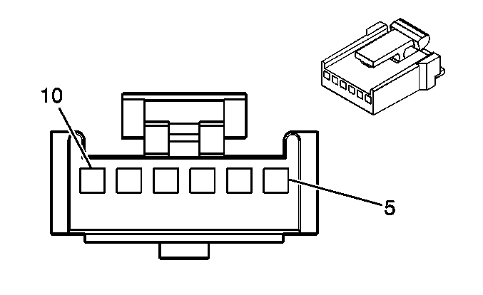
Connector Part Information
|
Pin | Wire Color | Circuit No. | Function |
|---|---|---|---|
5 | D-BU | 2272 | Amplifier Class 2 Serial Data |
6 | -- | -- | Not Used |
7 | L-GN/BK | 1354 | Drain Wire |
8 | D-GN | 1488 | Noise Compensation Microphone Supply Voltage |
9-10 | -- | -- | Not Used |
Audio Amplifier C3 (Premium-UQA)
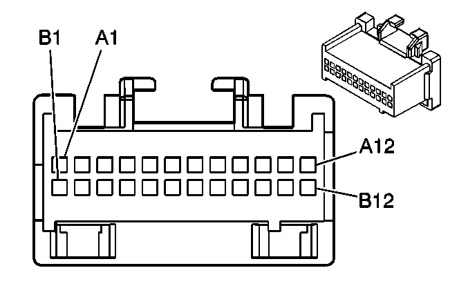
Connector Part Information
|
Pin | Wire Color | Circuit No. | Function |
|---|---|---|---|
A1 | BARE | 1573 | Drain Wire |
A2 | BN | 199 | Left Rear Speaker Output (+) |
A3 | YE | 116 | Left Rear Speaker Output (-) |
A4 | D-BU | 1857 | Left Front Midrange Speaker Output (+) |
A5 | L-BU | 1957 | Left Front Midrange Speaker Output (-) |
A6-A7 | -- | -- | Not Used |
A8 | D-GN | 1953 | Right Front Midrange Speaker Output (-) |
A9 | OG | 1853 | Right Front Midrange Speaker Output (+) |
A10 | L-BU | 115 | Right Rear Speaker Output (-) |
A11 | D-BU | 46 | Right Rear Speaker Output (+) |
A12 | -- | -- | Not Used |
B1 | BARE | 2012 | Drain Wire |
B2 | BARE | 2011 | Drain Wire |
B3-B7 | -- | -- | Not Used |
B8 | OG/BK | 1546 | Front Low Level Audio Signal (-) |
B9 | D-GN | 1947 | Left Front Low Level Audio Signal (-) |
B10 | TN | 511 | Left Front Low Level Audio Signal (+) |
B11 | L-GN | 512 | Right Front Low Level Audio Signal (+) |
B12 | -- | -- | Not Used |
Inflatable Restraint Steering Wheel Module Coil C4
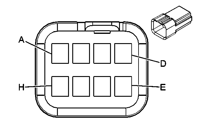
Connector Part Information
|
Pin | Wire Color | Circuit No. | Function |
|---|---|---|---|
A | YE | 1327 | DIC Fuel Signal |
B | D-BU | 894 | DIC Toggle Switch Signal |
C | D-GN | 1358 | DIC Switch Signal |
D | OG | 1816 | DIC Set/Reset Switch Signal |
E | WH | 2283 | 12-Volt Reference |
F | BK | 230 | Instrument Panel Lamps Dimming Control |
BK | 230 | Instrument Panel Lamps Dimming Control | |
G | L-GN | 1011 | Remote Radio Control Signal |
H | BK | 2250 | Ground |
BK | 2250 | Ground |
Noise Compensation Microphone (Premium-UQA)
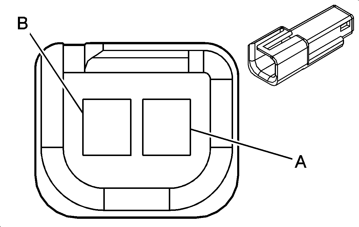
Connector Part Information
|
Pin | Wire Color | Circuit No. | Function |
|---|---|---|---|
A | D-GN | 1488 | Noise Compensation Microphone Supply Voltage |
B | L-GN/BK | 1354 | Drain Wire |
Radio Antenna Module
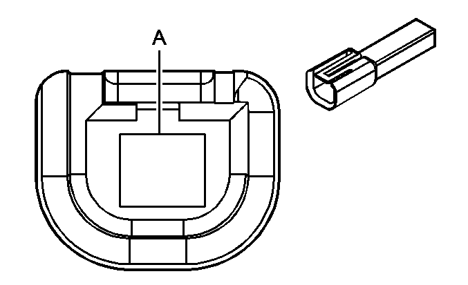
Connector Part Information
|
Pin | Wire Color | Circuit No. | Function |
|---|---|---|---|
A | GY | 1698 | Antenna Select Supply Voltage |
Radio C1

Connector Part Information
|
Pin | Wire Color | Circuit No. | Function |
|---|---|---|---|
A1 | OG | 1044 | Radio Class 2 Serial Data |
A2-A7 | -- | -- | Not Used |
A8 | TN | 511 | Left Front Low Level Audio Signal (+) (Premium) |
TN | 201 | Left Front Speaker Output (+) (Base) | |
A9 | D-GN | 1947 | Left Front Low Level Audio Signal (-) (Premium) |
GY | 118 | Left Front Speaker Output (-) (Base) | |
A10 | -- | -- | Not Used (Premium) |
L-BU | 115 | Right Rear Speaker Output (-) (Base) | |
A11 | -- | -- | Not Used (Premium) |
D-BU | 46 | Right Rear Speaker Output (+) (Base) | |
A12 | BK/WH | 751 | Signal Ground |
B1 | OG | 340 | Battery Positive Voltage |
B2 | -- | -- | Not Used |
B3 | GY | 1698 | Antenna Select Supply Voltagel |
B4 | BN/WH | 230 | Instrument Panel Lamps Dimming Control |
B5 | BK | 2250 | Ground |
B6-B7 | -- | -- | Not Used |
B8 | -- | -- | Not Used (Premium) |
BN | 199 | Left Rear Speaker Output (+) (Base) | |
B9 | -- | -- | Not Used (Premium) |
YE | 116 | Left Rear Speaker Output (-) (Base) | |
B10 | OG/BK | 1546 | Front Low Level Audio (-) (Premium) |
D-GN | 117 | Right Front Speaker Output (-) (Base) | |
B11 | L-GN | 512 | Right Front Low Level Audio Signal (Premium) |
L-GN | 200 | Right Front Speaker Output (+) (Base) | |
B12 | -- | -- | Not Used |
Speaker Assembly - LF Door (Base Radio)
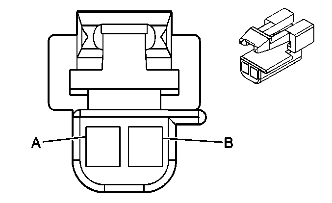
Connector Part Information
|
Pin | Wire Color | Circuit No. | Function |
|---|---|---|---|
A | GY | 118 | Left Front Speaker Output (-) |
B | TN | 201 | Left Front Speaker Output (+) |
Speaker - LF Door (Premium Radio-UQA)

Connector Part Information
|
Pin | Wire Color | Circuit No. | Function |
|---|---|---|---|
A | GY | 118 | Left Front Speaker Output (-) |
B | TN | 201 | Left Front Speaker Output (+) |
Speaker - LF Door Midrange (Premium-UQA)
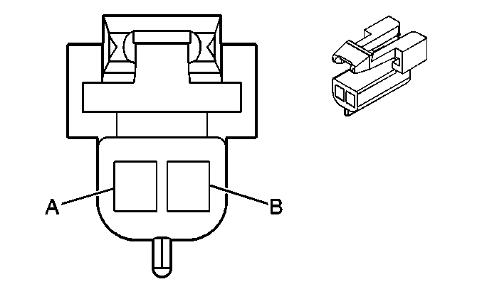
Connector Part Information
|
Pin | Wire Color | Circuit No. | Function |
|---|---|---|---|
A | L-BU | 1957 | Left Front Midrange Speaker Output (-) |
B | D-BU | 1857 | Left Front Midrange Speaker Output (+) |
Speaker - LR

Connector Part Information
|
Pin | Wire Color | Circuit No. | Function |
|---|---|---|---|
A | YE | 116 | Left Rear Speaker Output (-) |
B | BN | 199 | Left Rear Speaker Output (+) |
Speaker Assembly - RF Door (Base Radio)

Connector Part Information
|
Pin | Wire Color | Circuit No. | Function |
|---|---|---|---|
A | D-GN | 117 | Right Front Speaker Output (-) |
B | L-GN | 200 | Right Front Speaker Output (+) |
Speaker - RF Door (Premium-UQA)

Connector Part Information
|
Pin | Wire Color | Circuit No. | Function |
|---|---|---|---|
A | D-GN | 117 | Right Front Speaker Output (-) |
B | L-GN | 200 | Right Front Speaker Output (+) |
Speaker - RF Door Midrange (Premium-UQA)

Connector Part Information
|
Pin | Wire Color | Circuit No. | Function |
|---|---|---|---|
A | GN | 1953 | Right Front Midrange Speaker Output (-) |
B | OG | 1853 | Right Front Midrange Speaker Output (+) |
Speaker - RR

Connector Part Information
|
Pin | Wire Color | Circuit No. | Function |
|---|---|---|---|
A | L-BU | 115 | Right Rear Speaker Output (-) |
B | D-BU | 46 | Right Rear Speaker Output (+) |
Steering Wheel Controls - Left
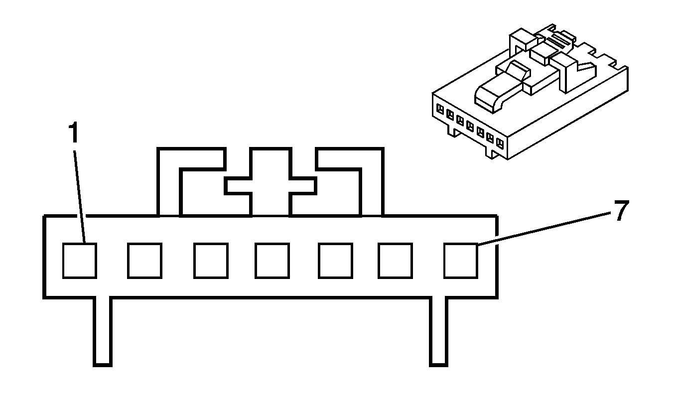
Connector Part Information
|
Pin | Wire Color | Circuit No. | Function |
|---|---|---|---|
1 | YE | 1327 | DIC Fuel Signal |
2 | OG | 1816 | DIC Set/Reset Switch Signal |
3 | BK | 230 | Instrument Panel Lamps Dimming Control |
4 | BK | 2250 | Ground |
5 | D-GN/WH | 1358 | DIC Switch Signal |
6 | D-BU | 894 | DIC Toggle Switch Signal |
7 | -- | -- | Not Used |
Steering Wheel Controls - Right
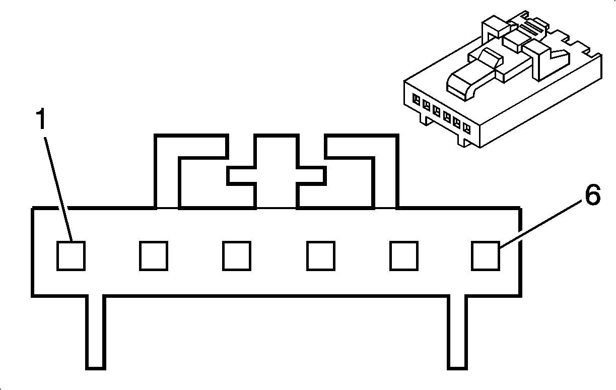
Connector Part Information
|

| |||||||
|---|---|---|---|---|---|---|---|
Connector Part Information |
| ||||||
Pin | Wire Color | Circuit No. | Function | ||||
1 | WH | 2283 | 12-Volt Reference | ||||
2 | -- | -- | Not Used | ||||
3 | BK | 230 | Instrument Panel Lamps Dimming Control | ||||
4 | -- | -- | Not Used | ||||
5 | BK | 2250 | Ground | ||||
6 | L-GN | 1011 | Remote Radio Control Signal | ||||
