Removal Procedure
- Cycle the folding top stowage lid open.
- Stop the cycle before the folding top panel is unlatched from the windshield header.
- Place a protective cover on all adjacent body panels and quarter panels.
- Remove the stowage compartment lid assembly. Refer to Folding Top Stowage Compartment Lid Replacement .
- Cycle the folding top until the front panel is unlatched from the windshield header.
- Remove the rear upper garnish molding. Refer to Rear Upper Garnish Molding Replacement in Interior Trim.
- Remove the front headliner. Refer to Roof Retractable Front Headlining Trim Panel Replacement in Interior Trim.
- Remove the side headliner. Refer to Roof Retractable Rear Side Headlining Trim Panel Replacement in Interior Trim.
- Remove the folding top front panel. Refer to Folding Top Front Panel Replacement .
- Remove the folding top rear panel. Refer to Folding Top Rear Panel Replacement .
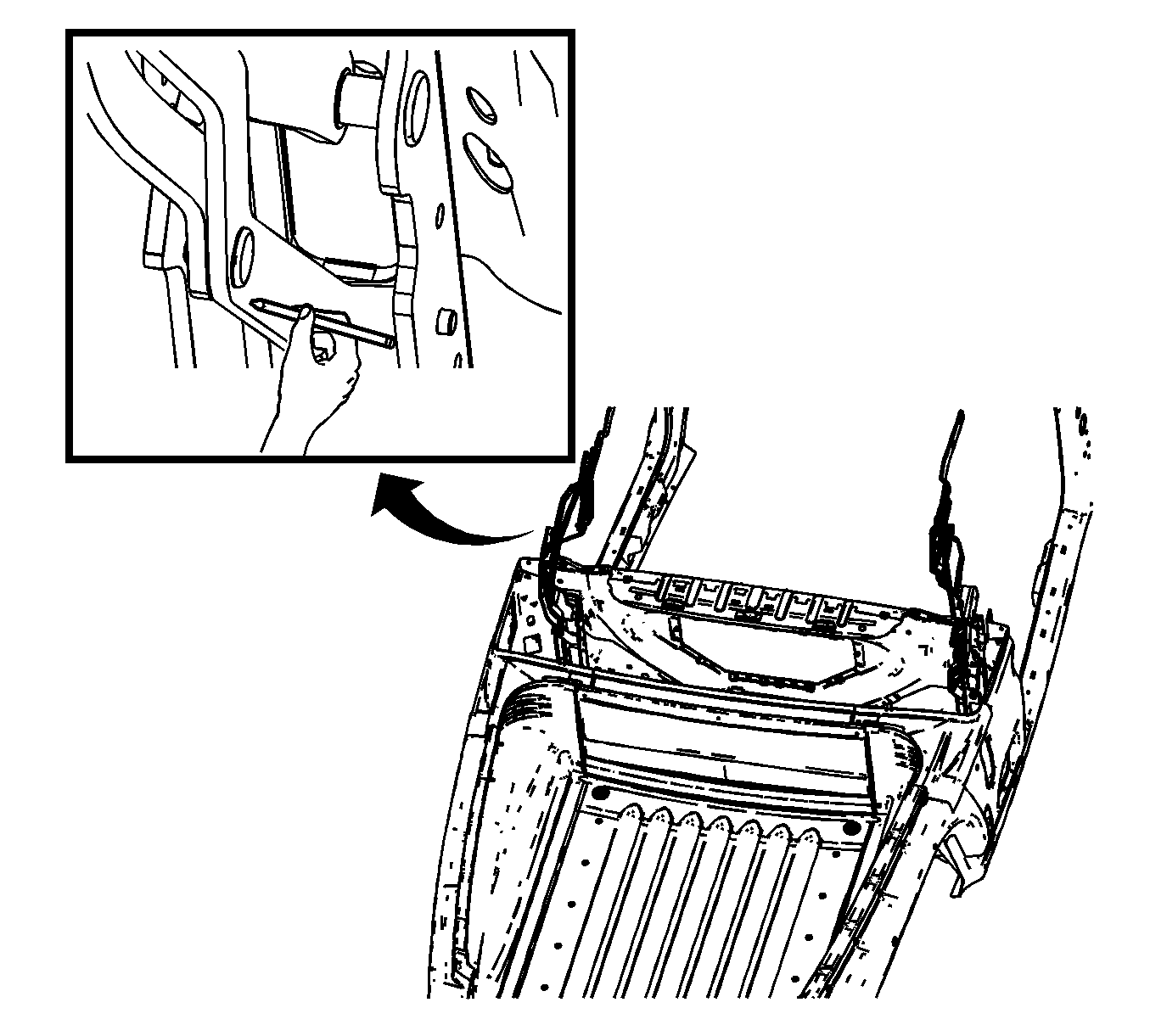
- Using a grease pencil or suitable marking device, mark alignment marks onto the bulkhead for realignment.
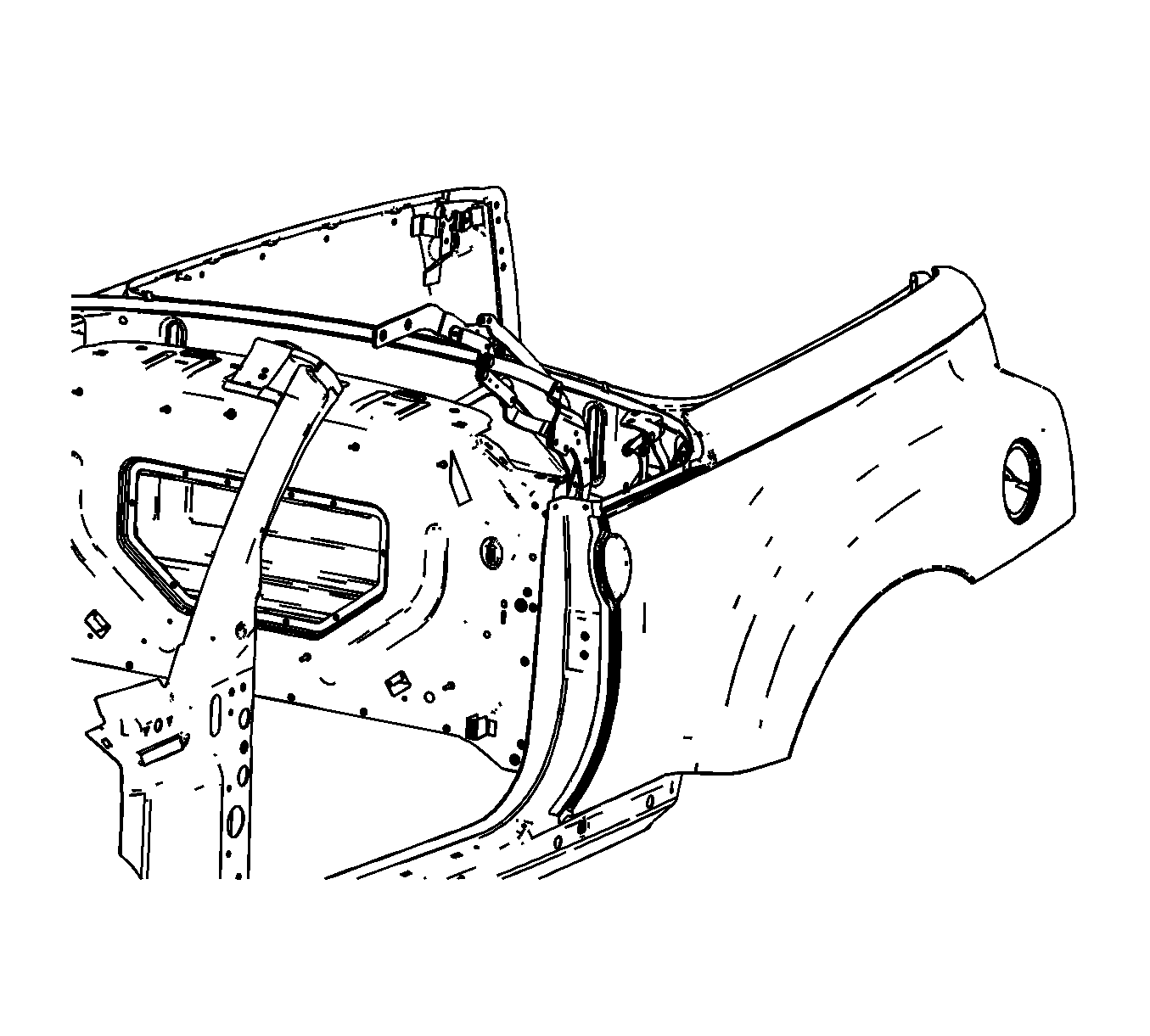
- Remove the necessary zip-ties to aid in removal of the folding top side rail assembly.
- Remove the lock pillar trim. Refer to Body Lock Pillar Trim Panel Replacement in Interior Trim.
- Remove the folding top side rail fasteners.
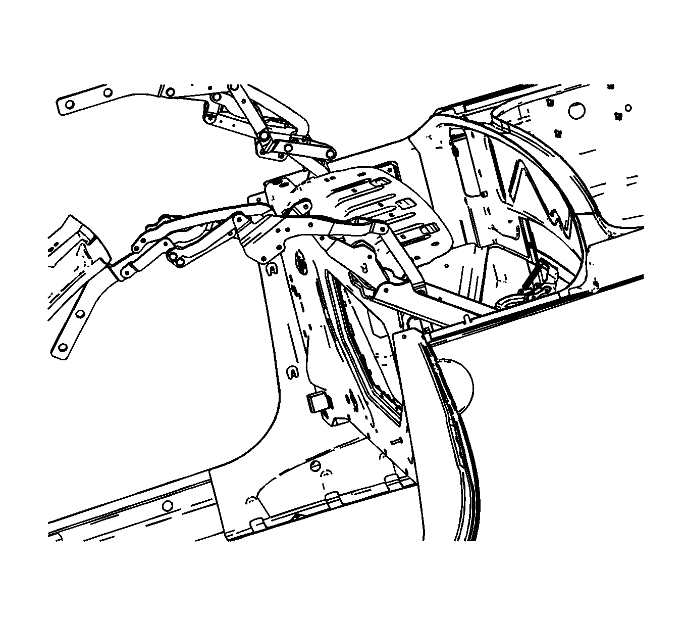
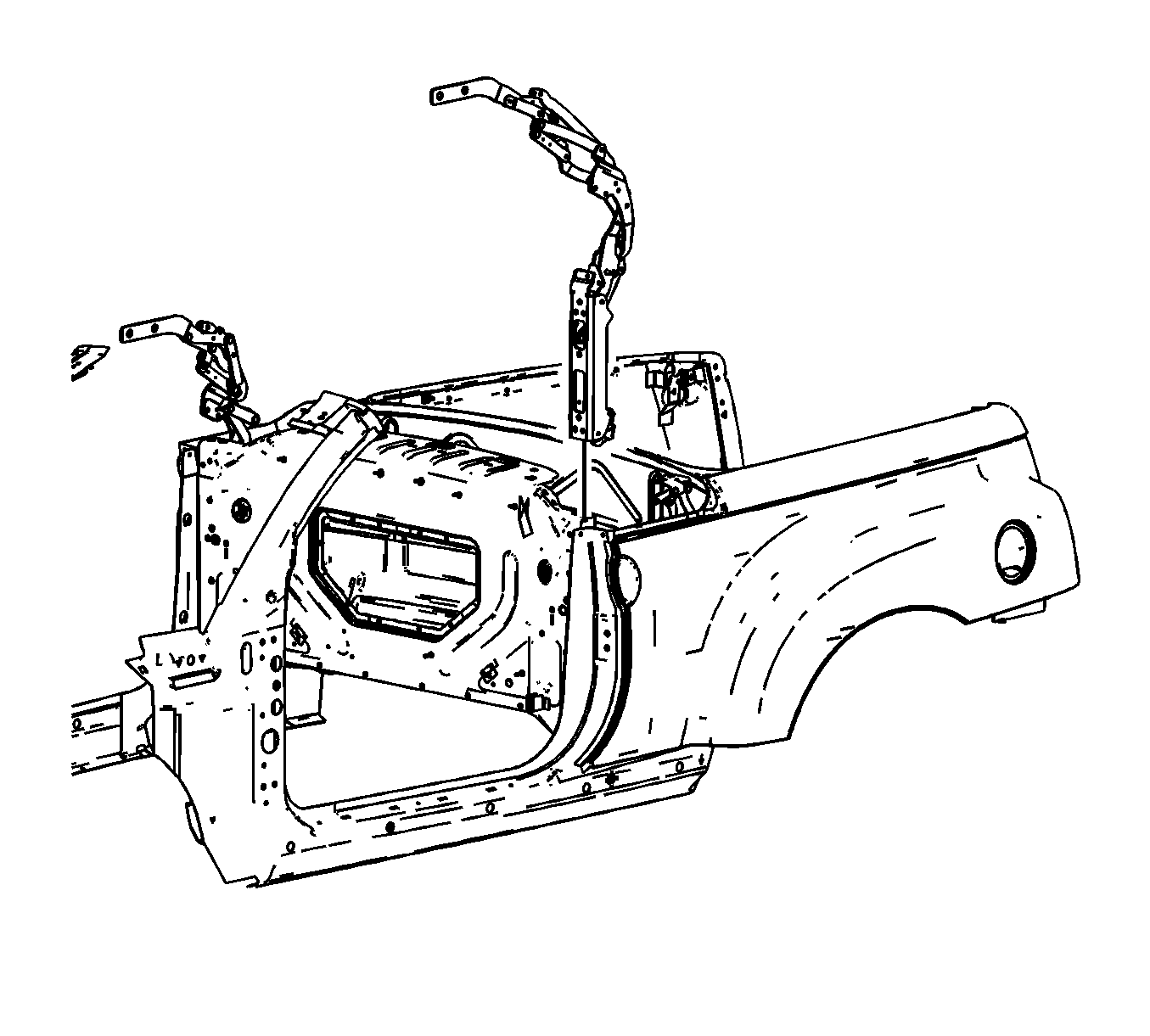
- Carefully lift the folding top side rail assembly upward to access the main lifting cylinder.
- Remove the lower retaining clip from the clevis pin. Note the spacer placement prior to removal.
- Remove the lower clevis pin and spacers.
- Remove the upper retaining clip from the clevis pin.
- While supporting the cylinder, remove the upper clevis pin.
- Remove the necessary zip-ties in order to remove the hoses from the main lift cylinder.
- Remove the side rail assembly from the vehicle.
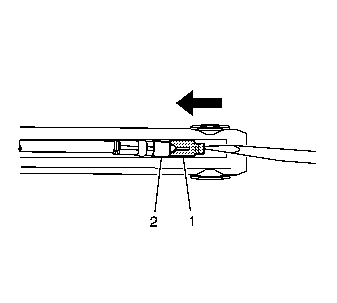
- Slide the gray cylinder cover back about 3 mm (0.118 in). Squeeze the black tab and disconnect the main cylinder position sensors electrical connectors. Cut the tie straps and electrical tape as needed. Mark the location of the cylinder sensors prior to removal.
- Place the main lift cylinder in a catch pan.
Caution: Refer to Eye Protection Caution in the Preface section.
Caution: Refer to Folding Top Hydraulic Pressure Caution in the Preface section.
Caution: Refer to Servicing Electrical Components Caution in the Preface section.
Disassembly Procedure
- Ensure that the ignition switch is in the OFF position and that the folding top has not been operated under power for at least 6 minutes.
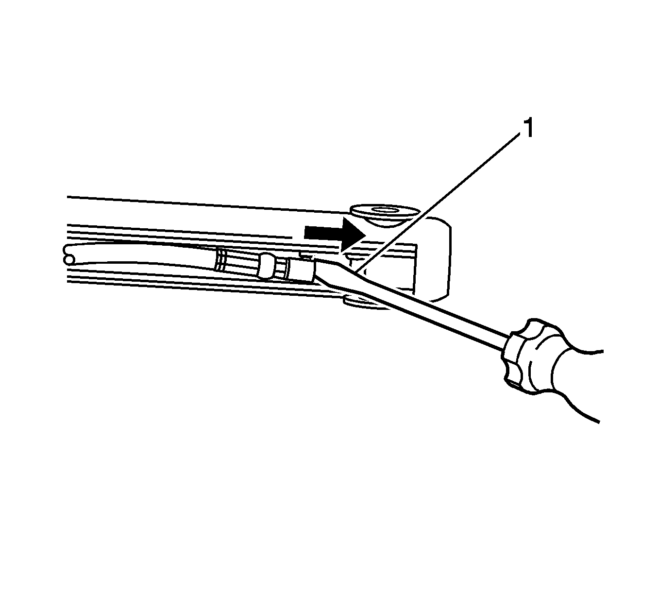
- Using a flat-bladed tool, release the retainer clips (1) from one of the cylinder hoses.
- Remove the cylinder hose retainer clips.
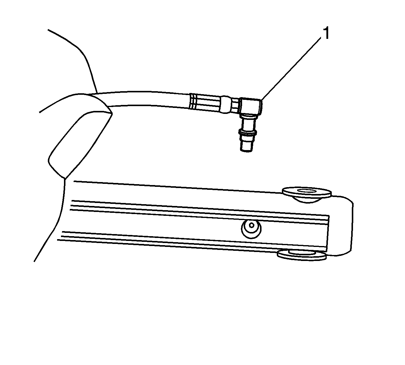
- Remove the cylinder hose (1). Use a clean shop towel to control any hydraulic fluid leakage.
- Using a plastic or wood tool, remove the cylinder hose O-ring (1).
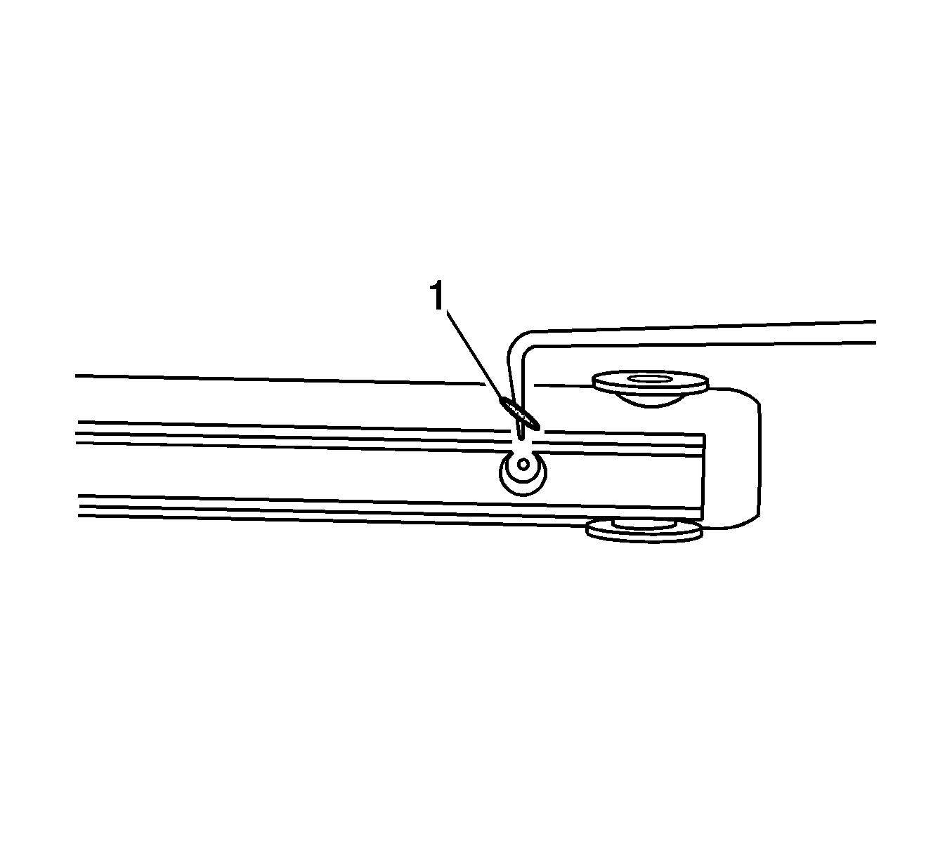
- Using a small flat-bladed tool, release one of the port plug retainer clips from the replacement cylinder.
- Remove the retainer clips from the replacement cylinder.
- Remove the port plug from the replacement cylinder.
- Remove the port plug O-ring (1) from the replacement cylinder.
Notice: Refer to Cylinder Hoses Notice in the Preface section.
Important: Once the cylinder hose of the port plug has been removed, DO NOT move the cylinder rod. Moving the cylinder rod will cause fluid to squirt out of the port.
Important: Before disconnecting the cylinder hoses, have the replacement cylinder ready.
Important: Replacement cylinders are prefilled with fluid. DO NOT remove the port plug from the cylinder until you are ready to connect the cylinder hose.
Assembly Procedure
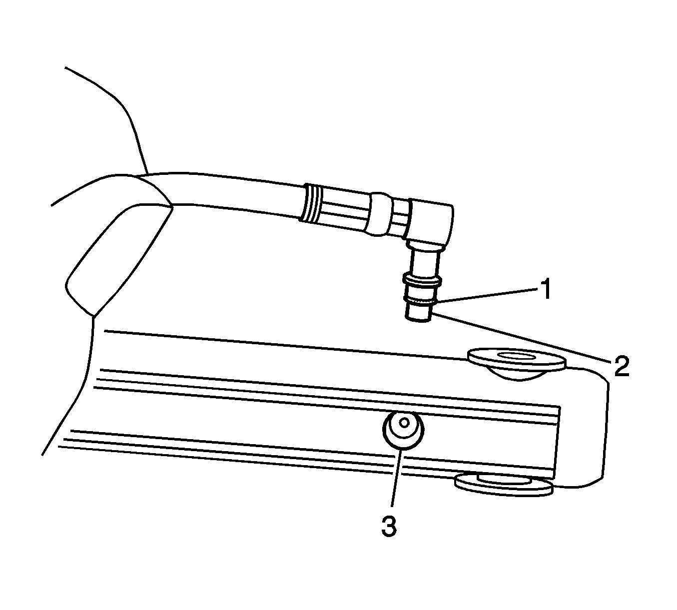
- Lubricate and install a new O-ring (1) onto the cylinder hose (2).
- Install the hose into the cylinder port (3). Press down on the hose until the hose is fully seated in the cylinder. Keep the hose as parallel with the cylinder as possible.
- Install the cylinder hose retainer clip (1). Inspect the retainer clip to ensure that the clip is fully seated around the hoses (2).
- Repeat this procedure for the other hose.
Installation Procedure
- Connect the main cylinder position sensors electrical connectors.
- Install the side rail assembly to the vehicle.
- While supporting the cylinder, install the upper clevis pin.
- Install the upper retaining clip for the clevis pin.
- Install the lower clevis pin and spacers.
- Install the lower retaining clip for the clevis pin.
- Connect the electrical connectors to the main cylinder position sensors. Fully seat the gray cover. Use new tie straps and re-tape as needed.
- Install the folding top side rail into the vehicle.
- Install the folding top side rail fasteners. Hand tighten the fasteners.
- Align the side rail to the alignment marks on the bulkhead.
- Install the lock pillar trim. Refer to Body Lock Pillar Trim Panel Replacement in Interior Trim.
- Route the down capture latch cable in the stowage compartment area.
- Install the removed zip-ties for proper cable/hose routing.
- Install the folding top rear panel into the vehicle. Refer to Folding Top Rear Panel Replacement .
- Install the folding top front panel into the vehicle. Refer to Folding Top Front Panel Replacement .
- Install the side headliner. Refer to Roof Retractable Rear Side Headlining Trim Panel Replacement in Interior Trim.
- Install the front headliner. Refer to Roof Retractable Front Headlining Trim Panel Replacement in Interior Trim.
- Install the rear upper garnish trim. Refer to Rear Upper Garnish Molding Replacement in Interior Trim.
- Cycle the folding top until the front panel is latched into the windshield header.
- Install the stowage compartment lid assembly. Refer to Folding Top Stowage Compartment Lid Replacement .
- Remove the protective covers from the vehicle.
- Bleed the hydraulic system. Refer to Folding Top Hydraulic System Bleeding Procedure .
- Inspect the hydraulic system for any oil leaks.
- Inspect the fluid level and add fluid as needed. Refer to Folding Top Fluid Addition .
- Inspect the folding top for proper operation. Refer to Power Folding Top Description and Operation .


Notice: Refer to Fastener Notice in the Preface section.
Tighten
Tighten the folding top side rail fasteners to 45 N·m (33 lb ft).
