Rear Axle Replacement 35 Series
Removal Procedure
Important: Observe and accurately reference mark all driveline components relative to the propeller shaft and axles before disassembly. These components include the propeller shafts, the drive axles, the pinion flanges, the output shafts, etc. All components must be reassembled in the exact relationship to each other as they were when removed. In addition, published specifications and torque values, as well as any measurements made prior to disassembly must be followed.
- Raise the vehicle. Refer to Lifting and Jacking the Vehicle .
- Place jack or utility stands (such as GMDE 123-B67313) at the front end of the vehicle.
- Support the axle with jack stands.
- Remove the tire and wheel assemblies. Refer to Tire and Wheel Removal and Installation .
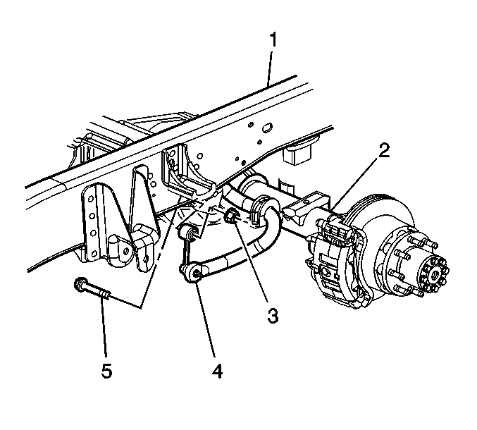
- Remove the stabilizer shaft link bolt (5) and the nut (3).
- Disconnect the upper stabilizer shaft link (4) from the frame.
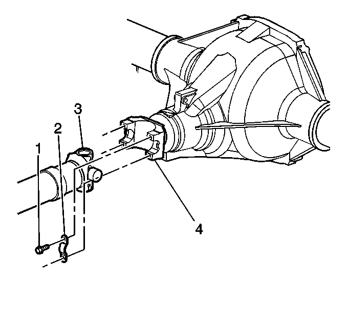
- Reference mark the rear propeller shaft (3) to the rear axle pinion yoke (4).
- Disconnect the propeller shaft from the axle.
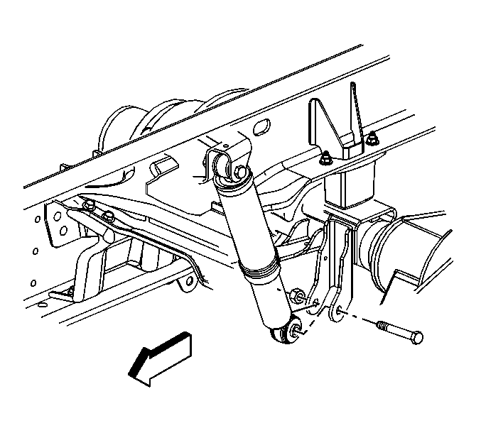
- Disconnect the lower mount of the shock absorbers.
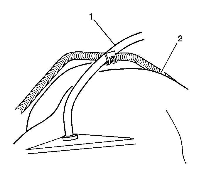
- Disconnect the vent hose (1).
- Disconnect the park brake cables. Refer to Parking Brake Rear Cable Replacement - Left Side and Parking Brake Rear Cable Replacement - Right Side .
- Disconnect the junction block.
- Disconnect the brake pipe.
- Disconnect the brake pipe fitting bracket from the brake assembly.
- Remove the brake calipers. Refer to Rear Brake Caliper Replacement .
- Support the calipers from the frame using a heavy gage mechanics wire.
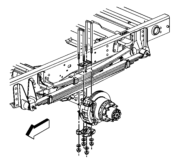
- Remove the nuts and the washers from the spring assembly U-bolts.
- Remove the U-bolts, the anchor plates and the spacers from the axle.
- Remove the axle with the aid of a hydraulic assist.
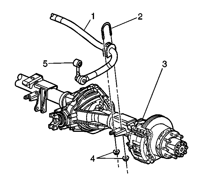
- Remove the stabilizer shaft U-bolt nuts (4) and the U-bolts (2) from the axle (3) (if necessary).
- Remove the stabilizer shaft (1) from the axle (if necessary).
Support the propeller shaft as necessary.
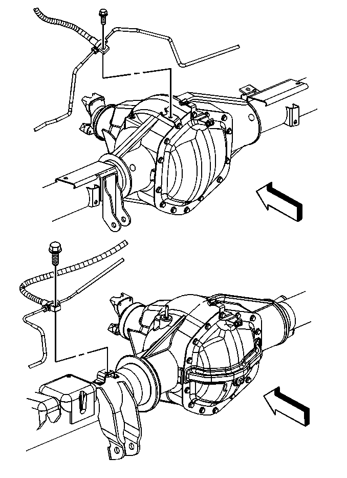
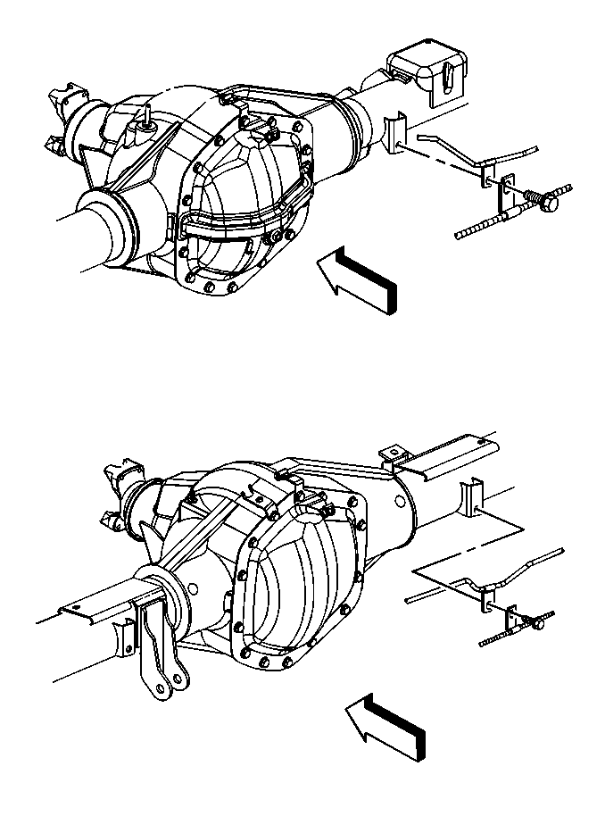
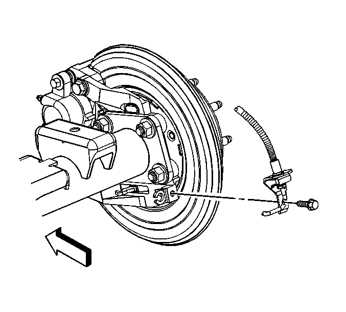
Notice: Support the brake caliper with heavy mechanic wire, or equivalent, whenever it is separated from its mount and the hydraulic flexible brake hose is still connected. Failure to support the caliper in this manner will cause the flexible brake hose to bear the weight of the caliper, which may cause damage to the brake hose and in turn may cause a brake fluid leak.
Installation Procedure
- Install the stabilizer shaft (1) to the axle (3) (if necessary).
- Install the stabilizer shaft clamps, the U-bolts (2), and the nuts (4) (if necessary).
- Place the axle under the vehicle.
- Raise the axle to the springs with the aid of a hydraulic assist.
- Install the spacers, the anchor plates and the U-bolts.
- Install the washers if equipped and the nuts to the U-bolts.
- Install the stabilizer shaft link to the frame (1) (if necessary).
- Install the stabilizer shaft link bolt (5) and the nut (3) (if necessary).
- Tighten the stabilizer shaft link bolts to 95 N·m (70 lb ft).
- Tighten the stabilizer shaft U-bolt nuts to 32 N·m (24 lb ft).
- Install the brake calipers. Refer to Rear Brake Caliper Replacement .
- Install the brake pipe fitting brackets.
- Install the brake pipe fitting bracket bolts.
- Install the brake pipe.
- Install the brake pipe bolts.
- Install the brake pipe junction block.
- Install the brake pipe junction block bolt.
- Connect the park brake cables. Refer to Parking Brake Rear Cable Replacement - Left Side and Parking Brake Rear Cable Replacement - Right Side .
- Connect the vent hose (1) to the axle vent fitting.
- Install the shock absorbers to the lower mount bracket.
- Install the shock absorber bolts and the nuts.
- Install the propeller shaft (3) to the pinion yoke (4).
- Install the propeller shaft yoke retaining clamps (2) and the bolts (1).
- Install the tire and wheel assemblies. Refer to Tire and Wheel Removal and Installation .
- Fill the axle with lubricant. Use the proper fluid. Refer to Approximate Fluid Capacities and Fluid and Lubricant Recommendations .
- Remove the jack and utility stands.
- Lower the vehicle.

Do not torque the stabilizer shaft U-bolt nuts at this time.
Align the axle with the springs.

Notice: Use the correct fastener in the correct location. Replacement fasteners must be the correct part number for that application. Fasteners requiring replacement or fasteners requiring the use of thread locking compound or sealant are identified in the service procedure. Do not use paints, lubricants, or corrosion inhibitors on fasteners or fastener joint surfaces unless specified. These coatings affect fastener torque and joint clamping force and may damage the fastener. Use the correct tightening sequence and specifications when installing fasteners in order to avoid damage to parts and systems.
Tighten
Tighten the nuts in a criss cross pattern to 150 N·m (110 lb ft).

Tighten

Tighten
Tighten the bolts to 22 N·m (16 lb ft).

Tighten
Tighten the bolts to 22 N·m (16 lb ft).

Tighten
Tighten the brake pipe junction block bolt to 22 N·m (16 lb ft).


Tighten
Tighten the shock absorber nuts to 95 N·m (70 lb ft).

Align the reference marks made during removal.
Tighten
Tighten the yoke retaining clamp bolts to 25 N·m (18 lb ft).
Rear Axle Replacement 15/25 Series
Removal Procedure
- Raise the vehicle. Refer to Lifting and Jacking the Vehicle .
- Place jack or utility stands (such as GMDE 123-B67313) at the front end of the vehicle.
- Drain the axle lubricant from the rear axle. Refer to Rear Axle Lubricant Replacement .
- Disconnect the propeller shaft. Refer to One-Piece Propeller Shaft Replacement or Two-Piece Propeller Shaft Replacement .
- Remove the tire and wheel assemblies. Refer to Tire and Wheel Removal and Installation .
- Disconnect the parking brake cable. Refer to Parking Brake Rear Cable Replacement - Left Side and Parking Brake Rear Cable Replacement - Right Side .
- Remove the brake line bracket bolts. Suspend the brake lines from the vehicle with heavy mechanics wire.
- Remove the brake calipers from the brake caliper mounting brackets. Do not disconnect the brake lines. Suspend the calipers from the vehicle with heavy mechanics wire. Refer to Rear Brake Caliper Replacement .
- Disconnect the shock absorbers from the axle brackets. Refer to Shock Absorber Replacement .
- Remove the vent hose from the rear axle vent fitting. Refer to Vent Hose Replacement .
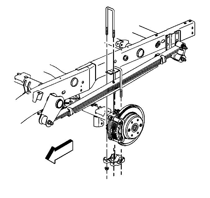
- Remove the nuts and the washers from the U-bolts.
- Remove the U-bolts, the spring plates and the spacers form the axle assembly.
- Lower the axle assembly.
Installation Procedure
- Place the rear axle assembly under the vehicle.
- Align the rear axle assembly with the springs.
- Connect the spacers, the spring plates and the U-bolts to the rear axle.
- Raise the rear axle assembly into position.
- Install the washers if equipped and the nuts to the U-bolts.
- Install the vent hose to the rear axle vent fitting. Refer to Vent Hose Replacement .
- Connect the shock absorbers to the rear axle. Refer to Shock Absorber Replacement .
- Install the brake calipers. Refer to Rear Brake Caliper Replacement .
- Install the brake lines and the brake line bracket bolts to the axle.
- Connect the parking brake cable. Refer to Parking Brake Rear Cable Replacement - Left Side and Parking Brake Rear Cable Replacement - Right Side .
- Install the tire and wheel assemblies. Refer to Tire and Wheel Removal and Installation .
- Connect the propeller shaft. Refer to One-Piece Propeller Shaft Replacement or Two-Piece Propeller Shaft Replacement .
- Fill the axle with lubricant. Use the proper fluid. Refer to Approximate Fluid Capacities and Fluid and Lubricant Recommendations .
- Remove the utility stands.
- Lower the vehicle.

Notice: Use the correct fastener in the correct location. Replacement fasteners must be the correct part number for that application. Fasteners requiring replacement or fasteners requiring the use of thread locking compound or sealant are identified in the service procedure. Do not use paints, lubricants, or corrosion inhibitors on fasteners or fastener joint surfaces unless specified. These coatings affect fastener torque and joint clamping force and may damage the fastener. Use the correct tightening sequence and specifications when installing fasteners in order to avoid damage to parts and systems.
Tighten
| • | 15 Series tighten the nuts in a criss cross pattern to 72 N·m (53 lb ft). |
| • | 25 series tighten the nuts in a criss cross pattern to 150 N·m (110 lb ft). |
Rear Axle Replacement 15 Series with Drum Brakes
Removal Procedure
- Raise support the vehicle. Refer to Lifting and Jacking the Vehicle .
- Place jack or utility stands (such as GMDE 123-B67313) at the front end of the vehicle.
- Drain the axle lubricant from the rear axle. Refer to Rear Axle Lubricant Replacement .
- Disconnect the propeller shaft. Refer to One-Piece Propeller Shaft Replacement .
- Remove the tire and wheel assemblies. Refer to Tire and Wheel Removal and Installation .
- Disconnect the parking brake cable. Refer to Parking Brake Rear Cable Replacement - Left Side and Parking Brake Rear Cable Replacement - Right Side .
- Remove the brake line bracket bolts. Suspend the brake lines from the vehicle with heavy mechanics wire.
- Disconnect the shock absorbers from the axle brackets. Refer to Shock Absorber Replacement .
- Remove the vent hose from the rear axle vent fitting. Refer to Vent Hose Replacement .
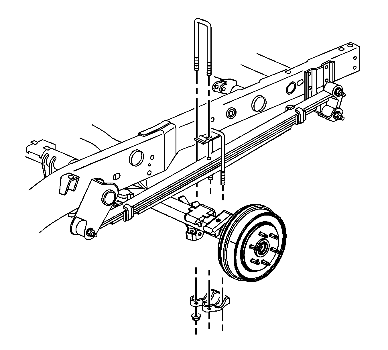
- Remove the nuts and the washers from the U-bolts.
- Remove the U-bolts, the spring plates and the spacers from the axle assembly.
- Lower the axle assembly.
Installation Procedure
- Place the rear axle assembly under the vehicle.
- Align the rear axle assembly with the springs.
- Connect the spacers, the spring plates and the U-bolts to the rear axle.
- Raise the rear axle assembly into position.
- Install the washers if equipped and the nuts to the U-bolts.
- Install the vent hose to the rear axle vent fitting. Refer to Vent Hose Replacement .
- Connect the shock absorbers to the rear axle. Refer to Shock Absorber Replacement .
- Install the brake lines and the brake line bracket bolts to the axle.
- Connect the parking brake cable. Refer to Parking Brake Rear Cable Replacement - Left Side and Parking Brake Rear Cable Replacement - Right Side .
- Install the tire and wheel assemblies. Refer to Tire and Wheel Removal and Installation .
- Connect the propeller shaft. Refer to One-Piece Propeller Shaft Replacement .
- Fill the axle with lubricant. Use the proper fluid. Refer to Approximate Fluid Capacities and Fluid and Lubricant Recommendations .
- Remove the utility stands.
- Lower the vehicle.

Notice: Refer to Fastener Notice in the Preface section.
Tighten
The nuts in a criss cross pattern to 72 N·m (53 lb ft).
