Tools Required
| • | J 43770
Main Lube Converter Relief Valve Spring Compressor |
| • | J 43772
Torque Converter Seal Installer |
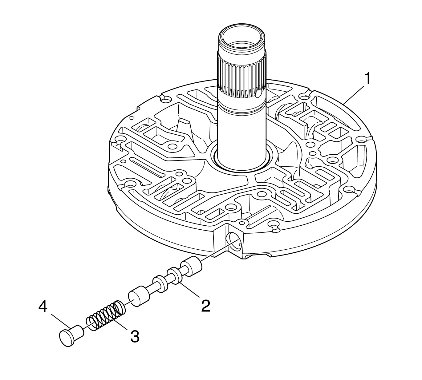
- Position the oil pump cover assembly (1) so that the rear of the assembly is facing down.
- Install the torque converter clutch (TCC) valve (2).
- Install the TCC valve spring (3) and stop (4).
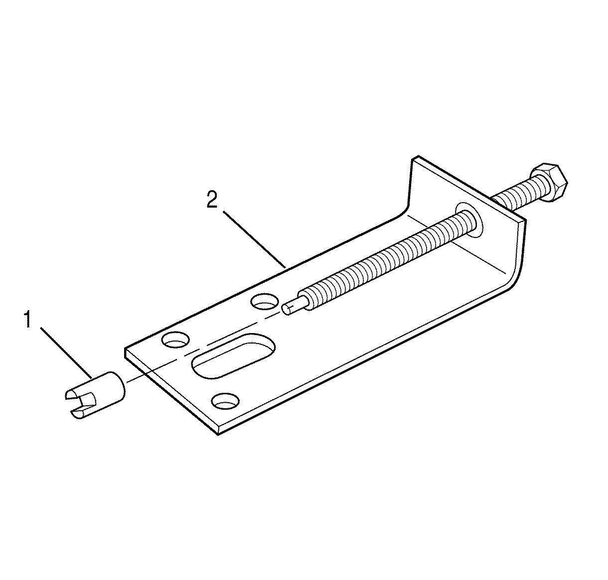
- Install
J 24459-5
(1) onto
J 43770
(2).
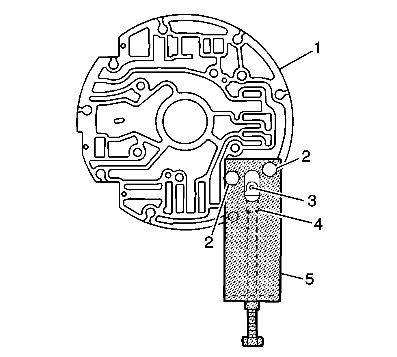
- Align
J 43770
(5) and
J 24459-5
(4)
with the oil pump cover so that the following conditions are met:
| • | The threaded rod is facing down. |
| • | Two bolt holes align with 2 bolt holes in the oil pump cover. |
- Install
J 43770
(5) onto the oil pump cover assembly (1).
- Install 2 oil pump cover retaining bolts (2).
- Align the slot in
J 24459-5
(4) to allow installing the retainer pin (3).
- Using
J 24459-5
(4) and
J 43770
(5), compress the TCC valve spring until the retainer pin (3) can be installed.
- Install the pin through oil pump cover (1). Make sure the pin is below the oil pump cover surface.
- Relieve the TCC valve spring tension.
- Remove
J 24459-5
(4) and
J 43770
(5).
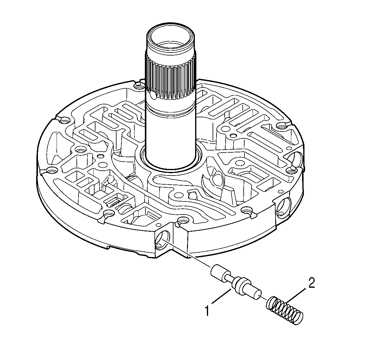
- Install the TCC relief valve (1) and spring (2).
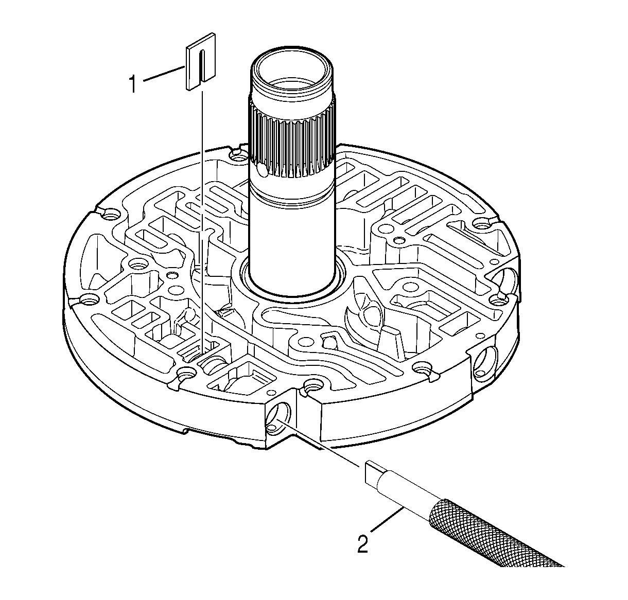
- Using
J 43773
(2), compress the TCC relief valve
spring until the retaining clip (1) can be installed.
- Install the clip. Make sure the retaining clip is below the surface of the oil pump cover.
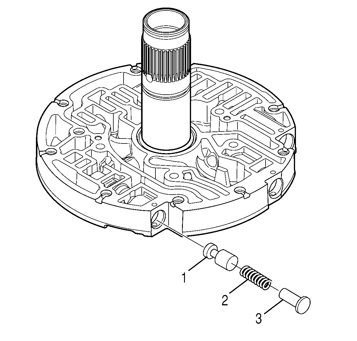
- Install the oil pump lube regulator valve (1).
- Install the oil pump lube regulator valve spring (2).
- Install the oil pump lube regulator valve stop (3).
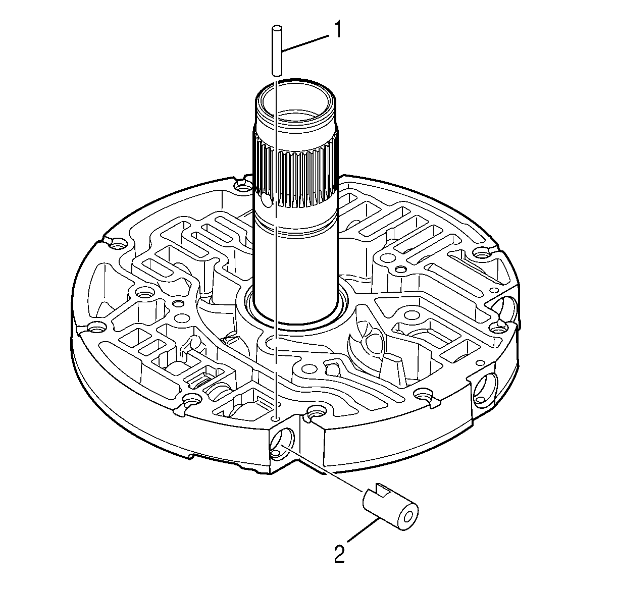
- Align the slot of
J 24459-5
(2) with retainer pin (1) hole.
- Using
J 24459-5
(2), compress the oil pump lube regulator valve spring until the retainer pin (1) can be installed.
- Install the retainer pin (1). Make sure the pin is below the surface of the oil pump cover.
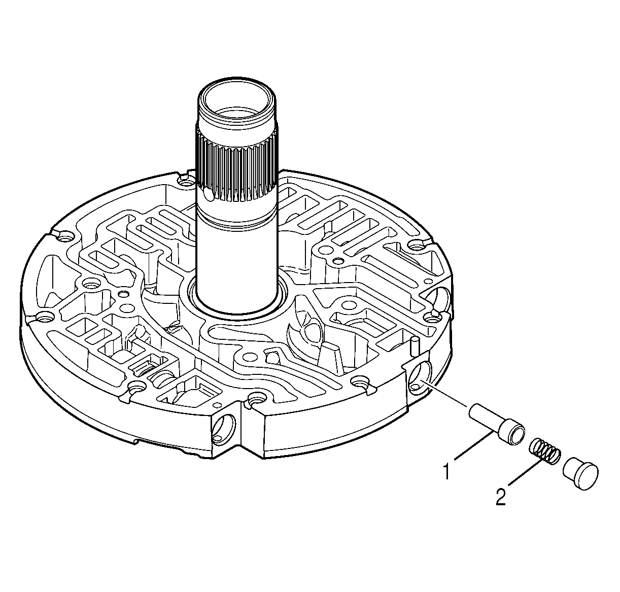
- Install the 1-2-3-4 clutch backfill valve (1).
- Install the 1-2-3-4 clutch backfill valve spring (2).
- Install the 1-2-3-4 clutch backfill valve stop.
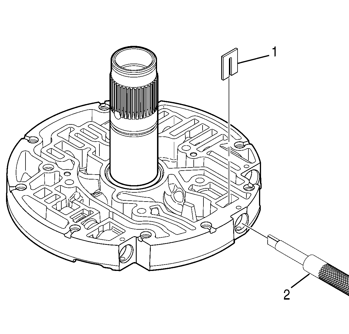
- Using
J 43773
(2), compress the 1-2-3-4 clutch backfill valve spring until the retaining clip (1)
can be installed.
- Install the retaining clip (1). Make sure the retaining clip is below the surface of the oil pump cover.
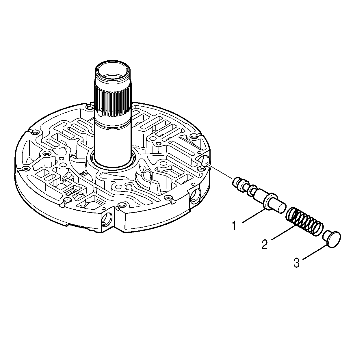
- Install the pressure regulator valve (1).
- Install the pressure regulator valve spring (2) and stop (3).

- Install
J 24459-5
(1) onto
J 43770
(2).
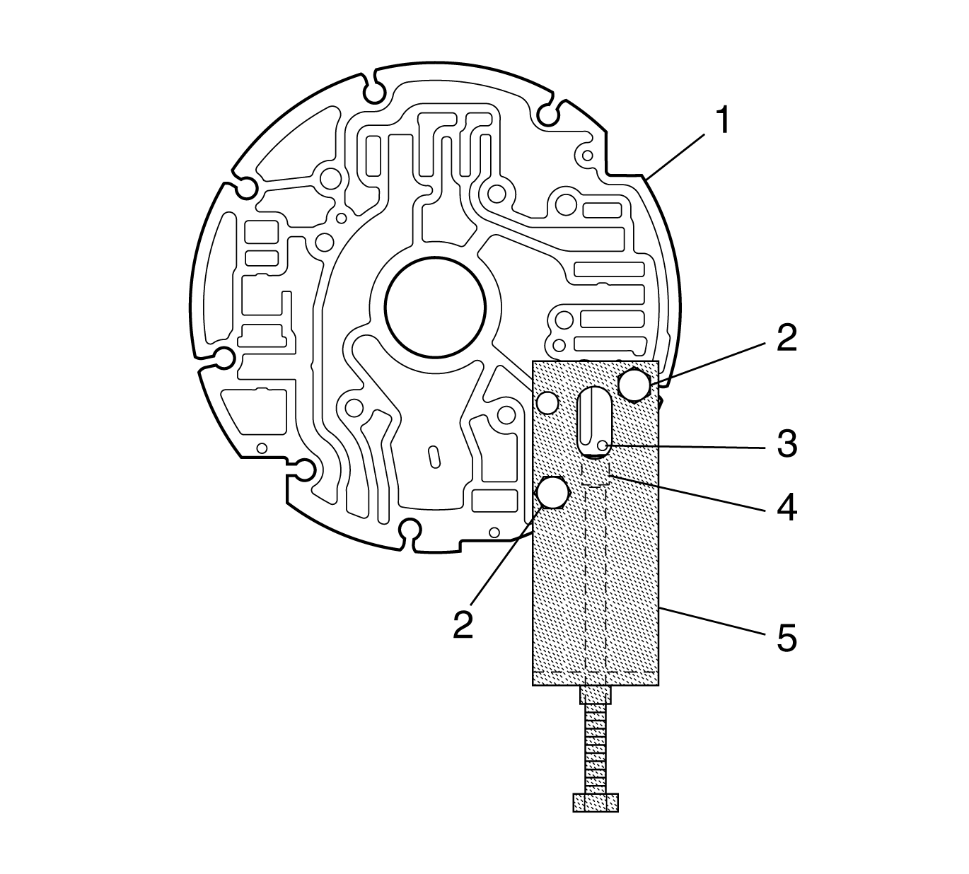
- Install
J 43770
(5) onto the oil pump cover assembly.
- Install 2 bolts (2).
- Align
J 24459-5
(4) slot with the retainer pin (3).
- Using
J 43770
and
J 24459-5
, compress the pressure regulator valve spring until the stop is past the pin hole.
- Install the retainer pin (3). Make sure the pin is below the surface of the oil pump cover.
- Relieve the spring pressure.
- Remove
J 24459-5
and
J 43770
.
Converter Housing/Oil Pump Cover Assembly
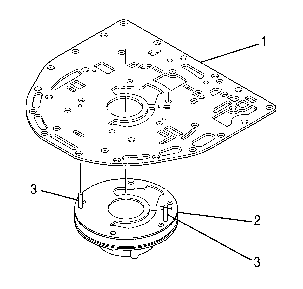
- Position the oil pump assembly (2) on the work table so that the rear of the pump is facing up.
- Align the locating pin holes in the torque converter housing to case channel plate (1) with the locating pins (3) in the oil pump assembly (2).
- Make sure the bolt holes in the torque converter housing to case channel plate (1) align with the bolt holes in the oil pump assembly (2).
- Install the torque converter housing to case channel plate (1) onto the oil pump assembly (2).
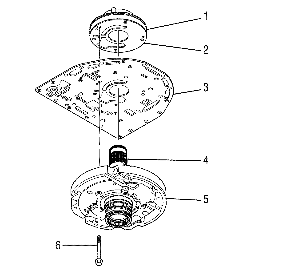
- Position the oil pump cover assembly (5) on the work table so that the stator shaft (4) is facing
up.
- Align, as a unit, the oil pump assembly (1) and the torque converter housing to case channel plate (3) so that the following conditions are met:
| • | Oil pump locating pins (2) align with the holes in the oil pump cover assembly (5). |
| • | The oil pump assembly bolt holes align with the bolt holes of the oil pump cover assembly. |
- Install, as a unit, the oil pump assembly (1) and the torque converter housing to case channel plate (2) onto the oil pump cover assembly (5).
Notice: Refer to Fastener Notice in the Preface section.
- Install 5 bolts (6).
Tighten
Tighten the bolts to 27 N·m (20 lb ft)
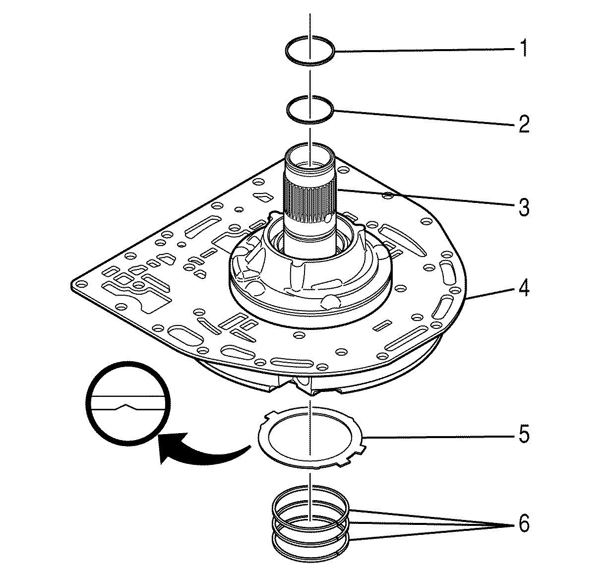
- Align the tangs of the thrust washer (5) with the slots at the base of the oil pump cover assembly rear hub.
- Install the thrust washer (5) onto the oil pump cover assembly. The thrust washer snaps into place.
- Install 3 new overlap seal rings (6) onto the oil pump cover assembly rear hub.
- Install a new overlap seal ring (2) onto the middle of the stator shaft (3).
- Install a new overlap seal ring (1) onto the front of the stator shaft (3).
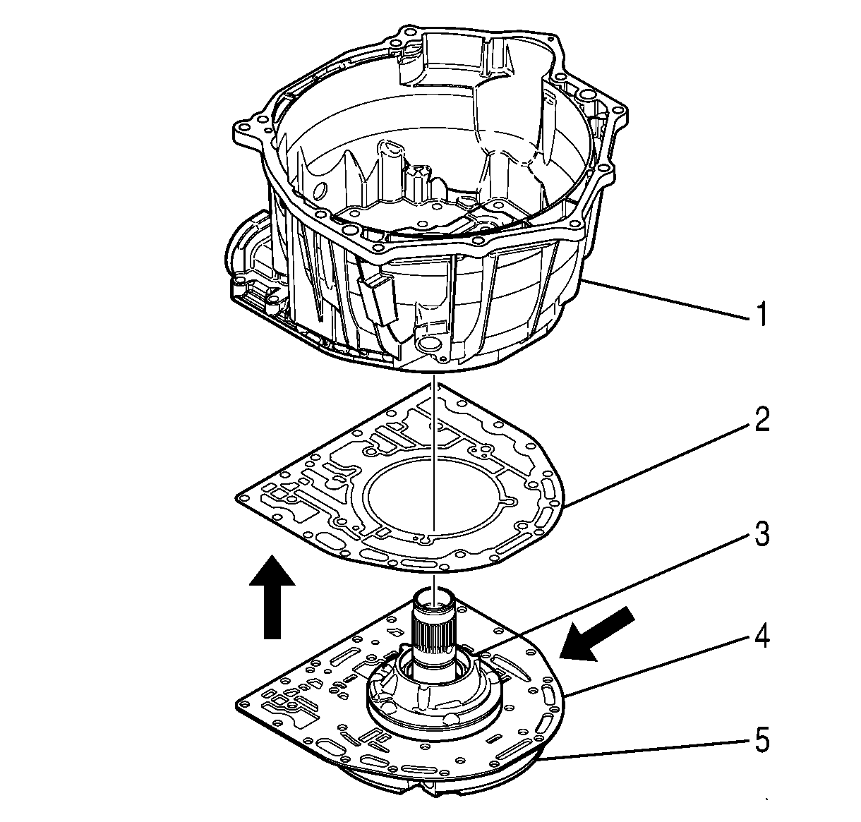
- Position the oil pump cover module (5) on the work table so that the stator shaft is facing up.
- Align the bolt holes of the torque converter housing to case channel plate gasket (2) with the bolt holes in the torque converter housing to case channel plate (4).
- Apply
J 36850
or an equivalent lubricant to the gasket face nearest the torque converter housing to case channel plate.
- Install the gasket onto the torque converter housing to case channel plate.
- Apply
J 36850
or an equivalent lubricant onto the outside diameter (OD) of the oil pump assembly (3).
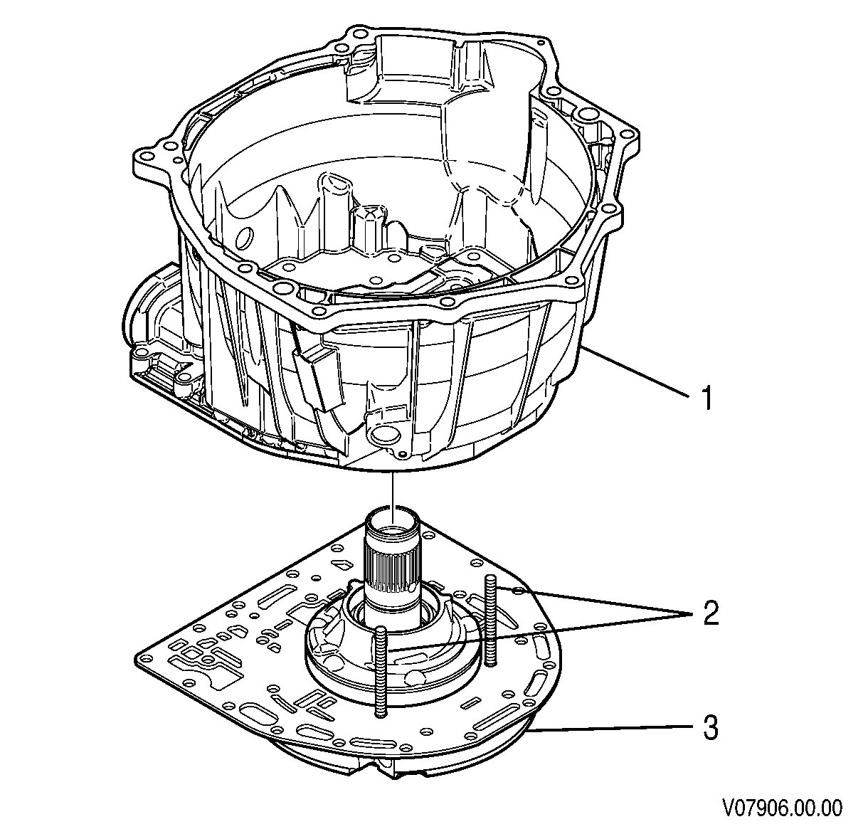
- Install 2 M10 x 1.5 guide bolts (2) into the oil pump cover module (3).
- Align the converter housing bolt holes with the bolt holes in the oil pump cover module.
- Install the converter housing onto the guide bolts and onto the oil pump cover module.
- Remove the guide bolts from the oil pump cover module.
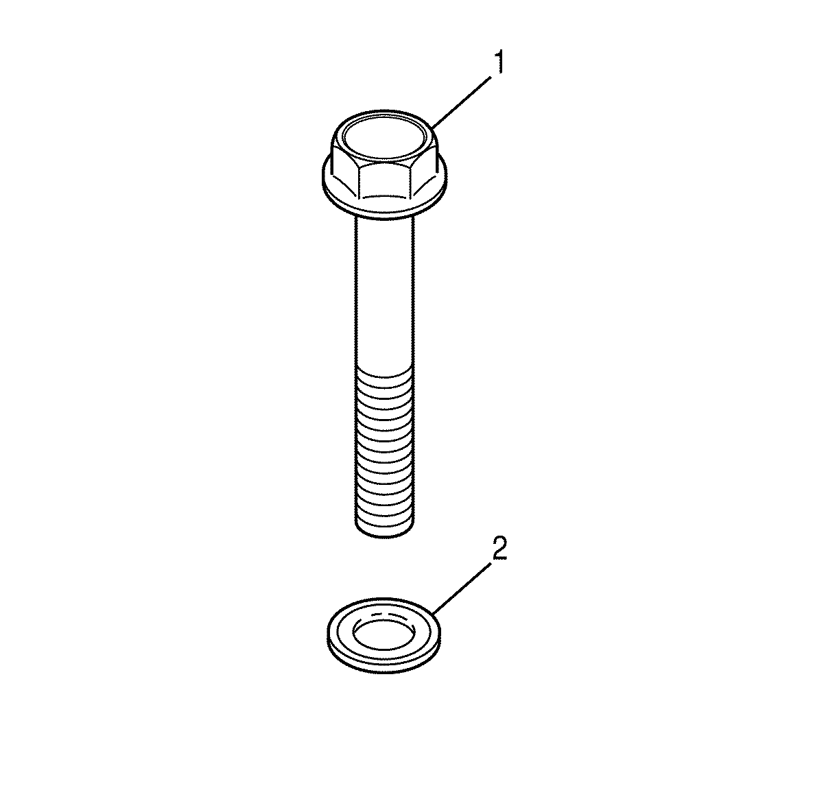
- Inspect the bolt seals (2) for nicks or other damage. Replace damaged seals.
- Install seals (2) onto 10 bolts (1).
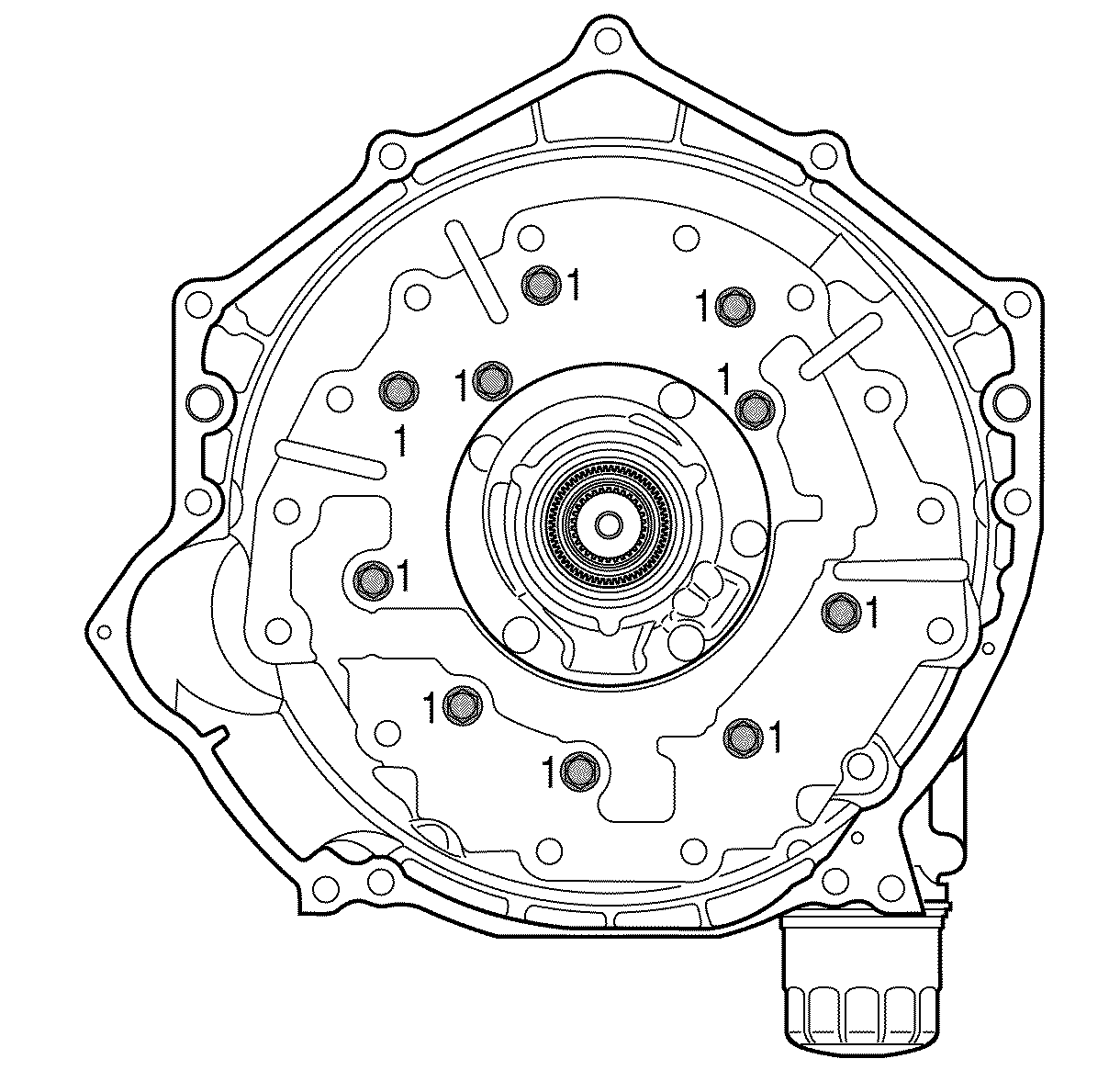
- Install 10 bolts (1) into the converter housing to retain the oil pump cover module.
Tighten
In a criss-cross pattern, tighten the bolts to 56 N·m (42 lb ft).
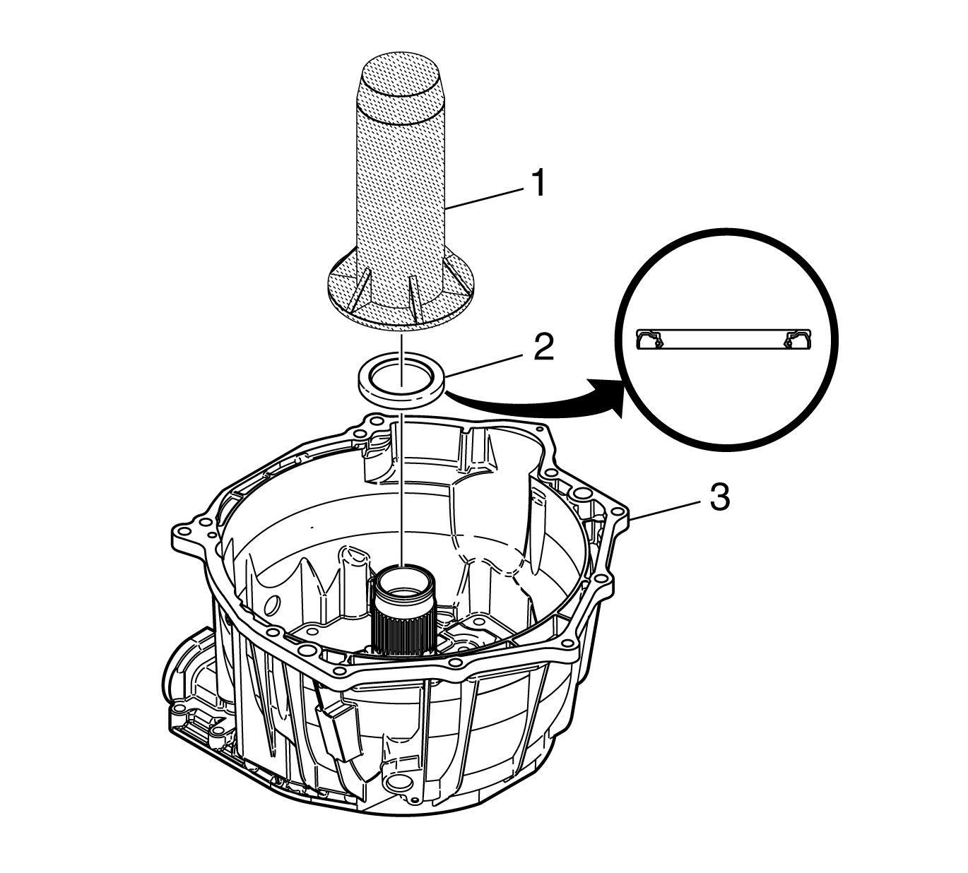
- Align the oil seal assembly (2) with the oil pump body so that the double edges face the pump body
hub.
- Using
J 43772
, install the oil seal assembly into the pump body hub.
Specification
The seal installed depth measurement is flush to 0.25 mm (0.010 in) below the oil pump body surface.


