For 1990-2009 cars only
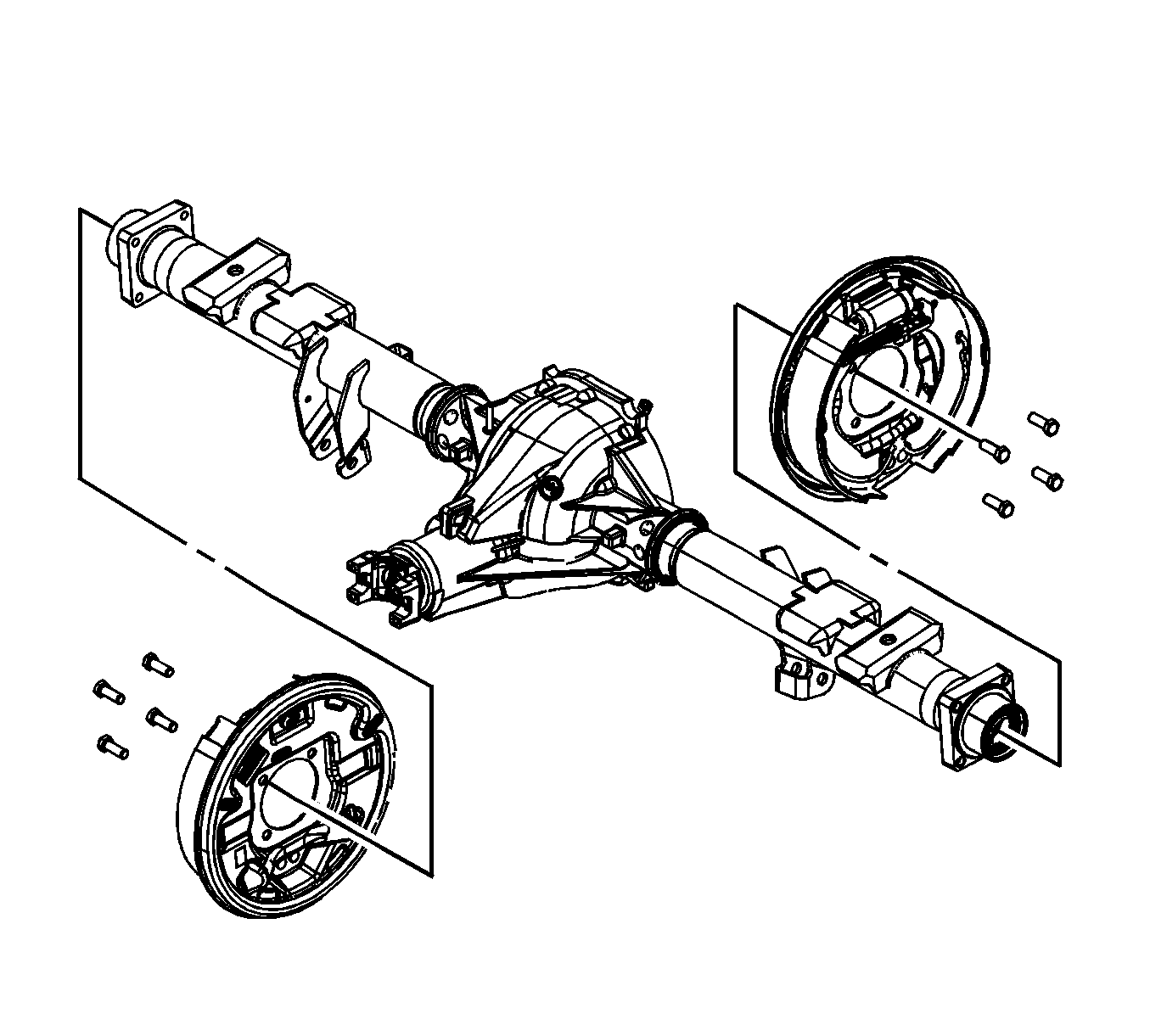
Rear Axle Housing Replacement With Rear Drum
Removal Procedure
- Remove the rear axle. Refer to Rear Axle Replacement.
- Remove the rear axle cover housing and gasket. Refer to Rear Axle Housing Cover and Gasket Replacement.
- Remove the rear wheel speed sensor. Refer to Rear Wheel Speed Sensor Replacement
- Remove the axle shafts. Refer to Rear Axle Shaft Replacement.
- Remove the rear brake assembly bolts.
- Remove the rear brake assemblies.
- Remove the rear axle shaft oil seals and bearings. Refer to Rear Axle Shaft Seal and/or Bearing Replacement.
- Remove the drive pinion shaft yoke and oil seal. Refer to Drive Pinion Flange/Yoke and/or Oil Seal Replacement.
- Remove the differential assembly. Refer to Drive Pinion and Ring Gear Replacement.
- Remove the drive pinion and the inner pinion bearing. Refer to Drive Pinion and Ring Gear Replacement.
- Remove the pinion bearing cups. Refer to Drive Pinion Bearings Replacement.

Installation Procedure
- Install the pinion bearing cups. Refer to Drive Pinion Bearings Replacement.
- Install the drive pinion oil seal. Refer to Drive Pinion Flange/Yoke and/or Oil Seal Replacement.
- Determine the selective shim thickness for the drive pinion. Refer to Pinion Depth Adjustment.
- Install the inner pinion bearing onto the drive pinion. Refer to Drive Pinion Bearings Replacement.
- Install the drive pinion. Refer to Drive Pinion and Ring Gear Replacement.
- Install the pinion yoke. Refer to Drive Pinion Flange/Yoke and/or Oil Seal Replacement.
- Install the differential assembly. Refer to Drive Pinion and Ring Gear Replacement.
- Adjust the differential side bearing preload. Refer to Differential Carrier Bearing Preload Adjustment.
- Adjust the drive pinion to ring gear backlash. Refer to Backlash Adjustment.
- Perform a gear tooth contact pattern check. Refer to Gear Tooth Contact Pattern Inspection.
- Install the rear axle shaft oil seals and bearings. Refer to Rear Axle Shaft Seal and/or Bearing Replacement.
- Install the rear brake assemblies.
- Install the rear brake assembly bolts.
- Install the axle shafts. Refer to Rear Axle Shaft Replacement
- Install the rear axle cover housing and gasket. Refer to Rear Axle Housing Cover and Gasket Replacement.
- Install the rear axle. Refer to Rear Axle Replacement.
- Install the rear wheel speed sensor. Refer to Rear Wheel Speed Sensor Replacement.

Caution: Refer to Fastener Caution in the Preface section.
Tighten
Tighten the bolts to 135 N·m (100 lb ft).
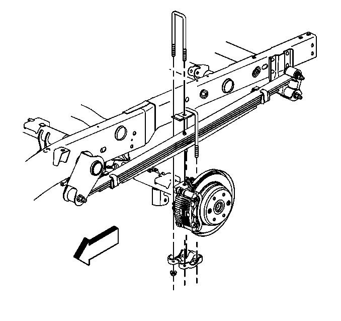
Rear Axle Housing Replacement With Rear Disc
Removal Procedure
- Raise the vehicle. Refer to Lifting and Jacking the Vehicle.
- Place jack or utility stands at the front end of the vehicle.
- Drain the axle lubricant from the rear axle. Refer to Rear Axle Lubricant Replacement.
- Disconnect the propeller shaft. Refer to One-Piece Propeller Shaft Replacement or Two-Piece Propeller Shaft Replacement.
- Remove the tire and wheel assemblies. Refer to Tire and Wheel Removal and Installation.
- Disconnect the wheel speed sensors.
- Disconnect the parking brake cable. Refer to Parking Brake Rear Cable Replacement - Left Side and Parking Brake Rear Cable Replacement - Right Side.
- Remove the brake line bracket bolts. Suspend the brake lines from the vehicle with heavy mechanics wire.
- Remove the brake calipers from the brake caliper mounting brackets. Do not disconnect the brake lines. Suspend the calipers from the vehicle with heavy mechanics wire. Refer to Rear Brake Caliper Replacement.
- Disconnect the shock absorbers from the axle brackets. Refer to Shock Absorber Replacement.
- Remove the vent hose from the rear axle vent fitting. Refer to Vent Hose Replacement.
- Remove the nuts and the washers from the U-bolts.
- Remove the U-bolts, the spring plates and the spacers form the axle assembly.
- Lower the axle assembly.

| • | For non-hybrid vehicles less than 3900 kg (8600 lb), refer to Rear Wheel Speed Sensor Replacement. |
| • | For non-hybrid vehicles greater than 3900 kg (8600 lb), refer to Rear Wheel Speed Sensor Replacement. |
Installation Procedure
- Place the rear axle assembly under the vehicle.
- Align the rear axle assembly with the springs.
- Connect the spacers, the spring plates and the U-bolts to the rear axle.
- Raise the rear axle assembly into position.
- Install the washers if equipped and the nuts to the U-bolts.
- Install the vent hose to the rear axle vent fitting. Refer to Vent Hose Replacement.
- Connect the shock absorbers to the rear axle. Refer to Shock Absorber Replacement.
- Install the brake calipers. Refer to Rear Brake Caliper Replacement.
- Install the brake lines and the brake line bracket bolts to the axle.
- Connect the parking brake cable. Refer to Parking Brake Rear Cable Replacement - Left Side and Parking Brake Rear Cable Replacement - Right Side.
- Connect the wheel speed senors.
- Install the tire and wheel assemblies. Refer to Tire and Wheel Removal and Installation.
- Connect the propeller shaft. Refer to One-Piece Propeller Shaft Replacement or Two-Piece Propeller Shaft Replacement.
- Fill the axle with lubricant. Use the proper fluid. Refer to Approximate Fluid Capacities and Fluid and Lubricant Recommendations.
- Remove the utility stands.
- Lower the vehicle.

Caution: Refer to Fastener Caution in the Preface section.
Tighten
| • | 15 Series tighten the nuts in a criss cross pattern to 72 N·m (53 lb ft). |
| • | 25 series tighten the nuts in a criss cross pattern to 150 N·m (110 lb ft). |
| • | For non-hybrid vehicles less than 3900 kg (8600 lb), refer to Rear Wheel Speed Sensor Replacement. |
| • | For non-hybrid vehicles greater than 3900 kg (8600 lb), refer to Rear Wheel Speed Sensor Replacement. |
