For 1990-2009 cars only
Removal Procedure
- Remove the fender brace. Refer to Front Fender Rear Upper Brace Replacement.
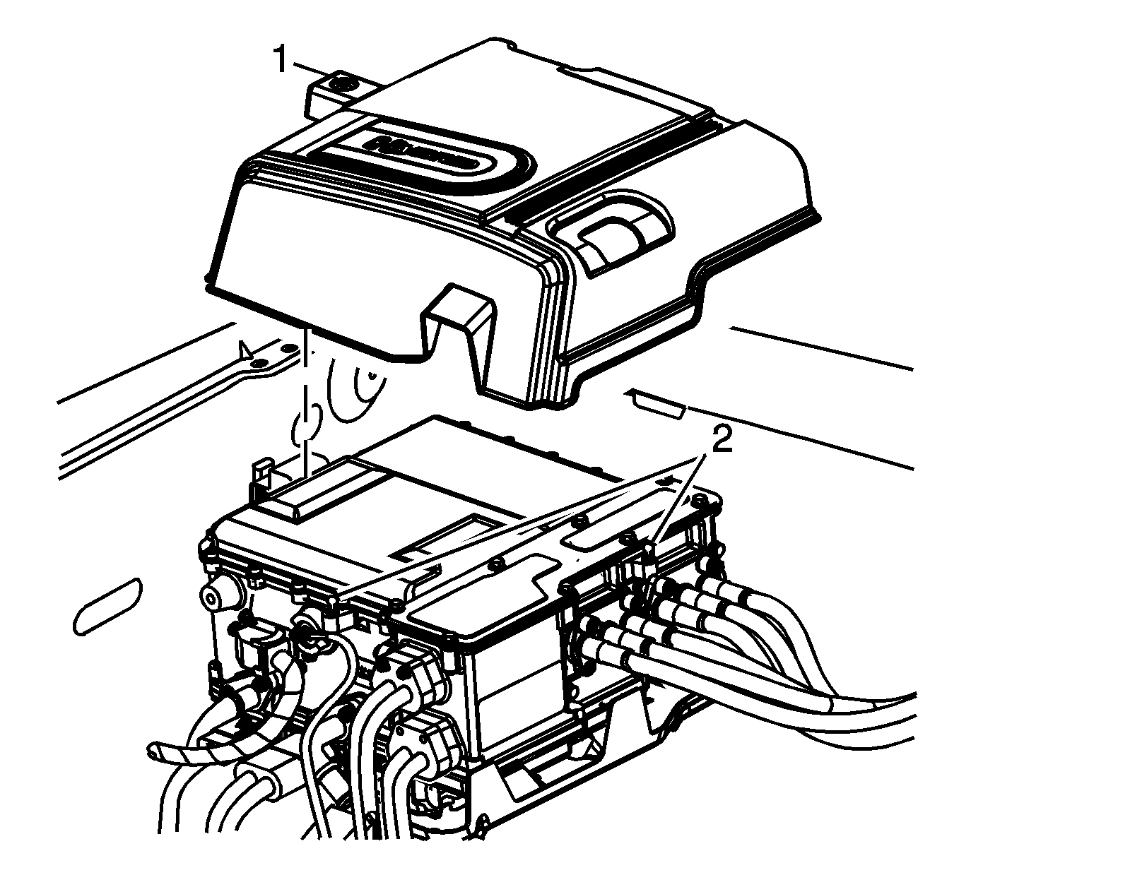
- Loosen the sight shield fastener (1) and lift the sight shield from the ball studs (2).
- Perform the High Voltage Disabling procedure. Refer to High Voltage Disabling.

Note: Removing the sight shield disengages the High Voltage Interlock Circuit (HVIC). The sight shield mounting fastener must be installed and properly tightened for the HVIC to be closed. Failure to properly tighten the sight shield fastener may result in an open HVIC condition and DTCs.
Danger: Always perform the High Voltage Disabling procedure prior to servicing any High Voltage component or connection. Personal Protection Equipment (PPE) and proper procedures must be followed.
The High Voltage Disabling procedure will perform the following tasks:| • | Identify how to disable high voltage. |
| • | Identify how to test for the presence of high voltage. |
| • | Identify condition under which high voltage is always present and personal protection equipment (PPE) and proper procedures must be followed. |
Installation Procedure
- Install the sight shield onto the ball studs (2) and tighten the sight shield fastener (1). Tighten the fastener to 5 N·m (44 lb in).
- Install the fender brace. Refer to Front Fender Rear Upper Brace Replacement.
- Enable high voltage. Refer to High Voltage Enabling.

Note: The sight shield mounting fastener must be installed and tightened. Failure to properly tighten the sight shield fastener may result in an open High Voltage Interlock Circuit (HVIC) condition and DTCs.
