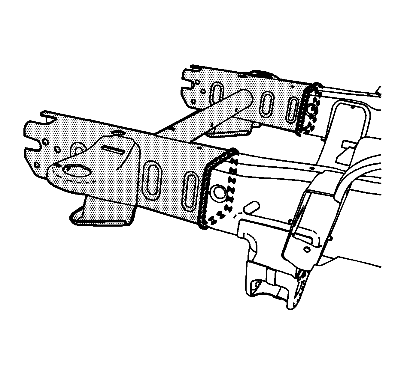
Removal Procedure
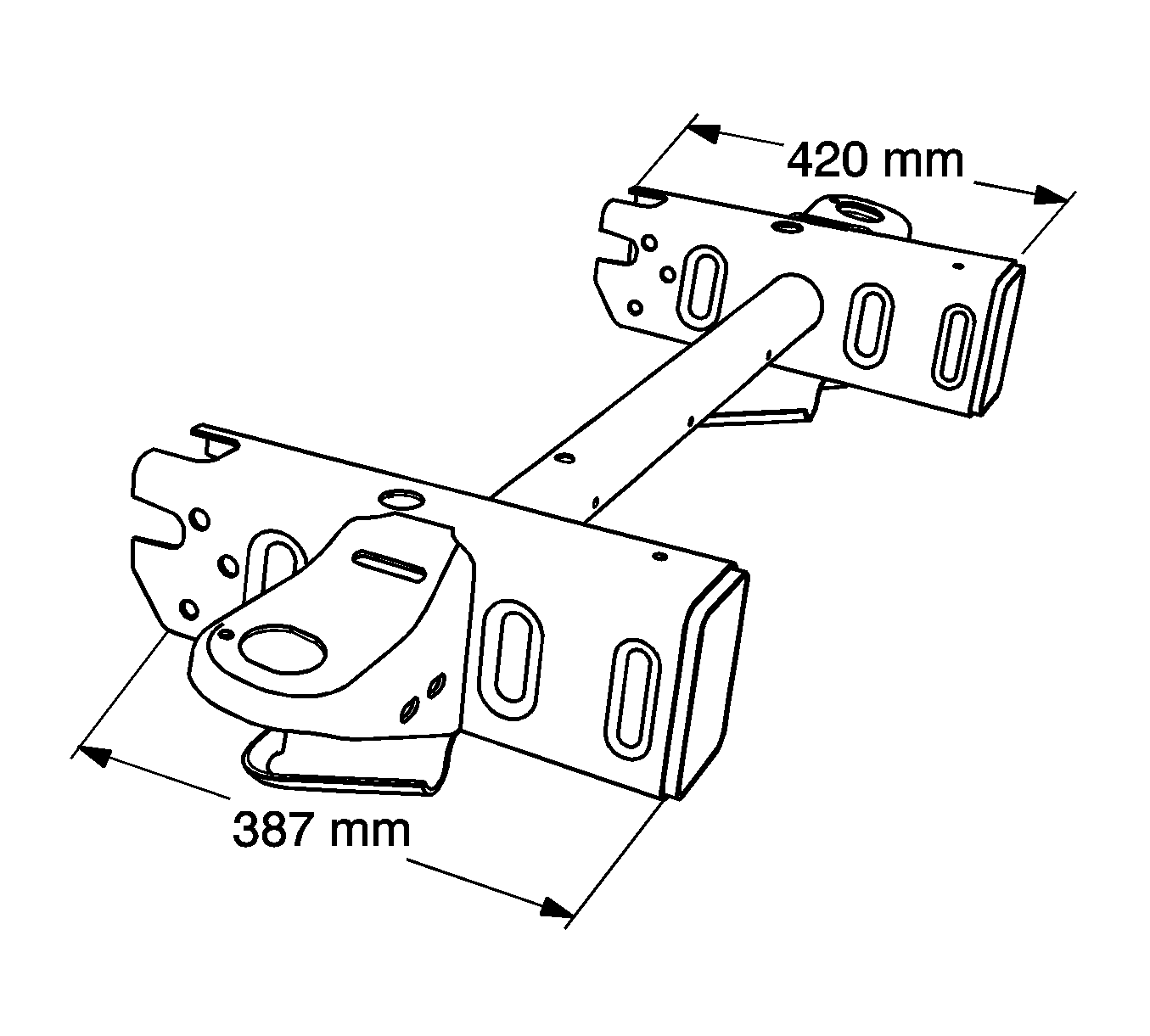
The re-designed frame assembly for the new Pick-Up and Utility Trucks is a mild steel, hydroformed frame assembly. A pre-sleeved replacement front frame service section, consisting of the left and right frame rail ends, body, mounting brackets and front connecting cross tube is available. Replacement bolt-on front bumper brackets are available and must be ordered separately.
- Disable the SIR system. Refer to SIR Disabling and Enabling.
- Disconnect the negative battery cable. Refer to Battery Negative Cable Disconnection and Connection.
- Remove all of the related panels and components.
- Locate and mark the sectioning location by using at least 2 of the measurements below for each frame rail:
- Apply masking tape completely around the frame rail next to the sectioning location as shown.
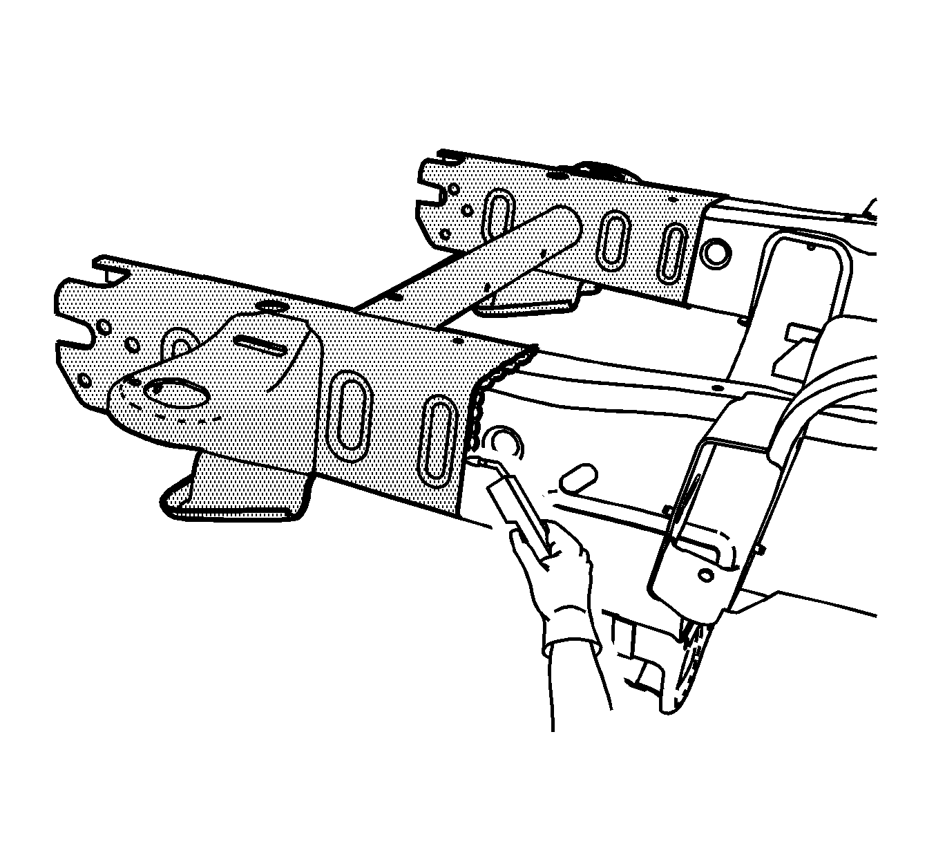
- Cut each frame rail at the front edge of the tape line using a reciprocating saw or equivalent, as shown.
- Remove the damaged frame section.
Warning: Refer to Approved Equipment for Collision Repair Warning in the Preface section.
Warning: Refer to Collision Sectioning Warning in the Preface section.
Note: Perform all of the steps on both of the rails for complete module replacement.
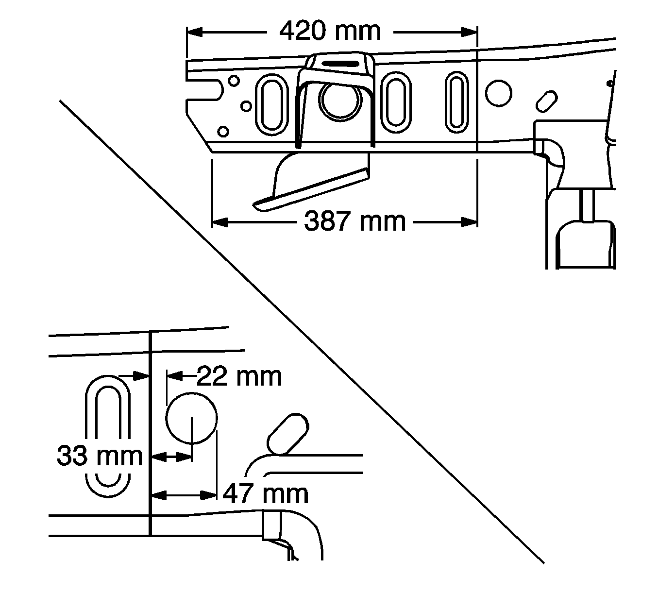
| • | Top of the frame rail edge rearward 420 mm (16 1/2 in) (with bumper bracket removed) |
| • | Bottom of the frame rail edge rearward 387 mm (15 3/16 in) (with bumper bracket removed) |
| • | Front edge of the gage hole forward 22 mm (7/8 in) |
| • | Center of the gage hole forward 33 mm (1 1/4) |
| • | Rear edge of the gage hole forward 47 mm (1 7/8 in) |
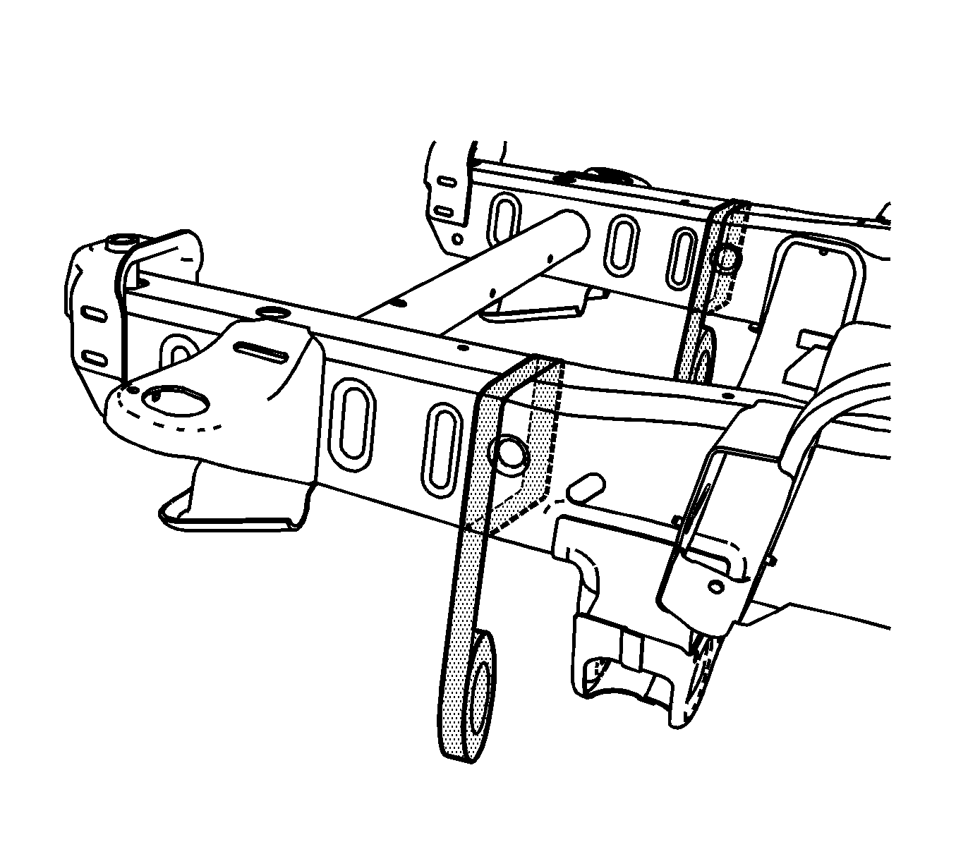
Note: Line up the masking tape with the tape edge facing the front of the vehicle on the sectioning location.
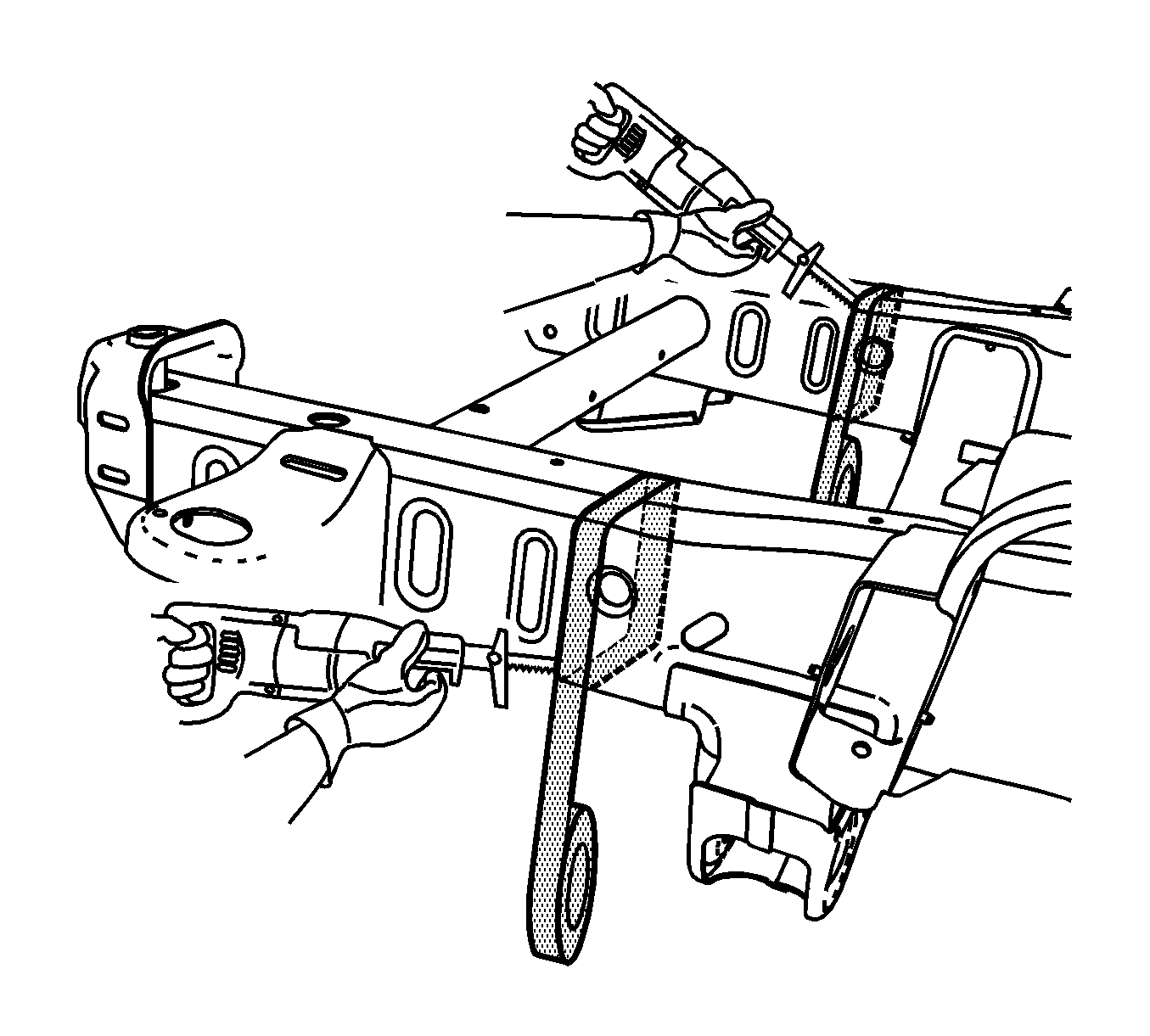
Note: The tape edge facing the front of the vehicle is the proper cut location.
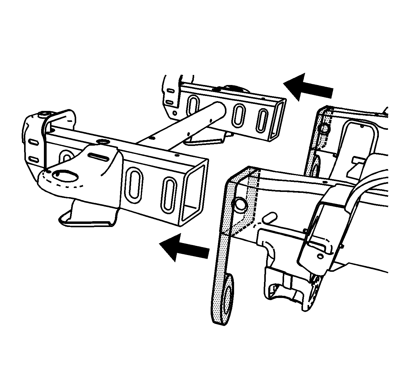
Installation Procedure
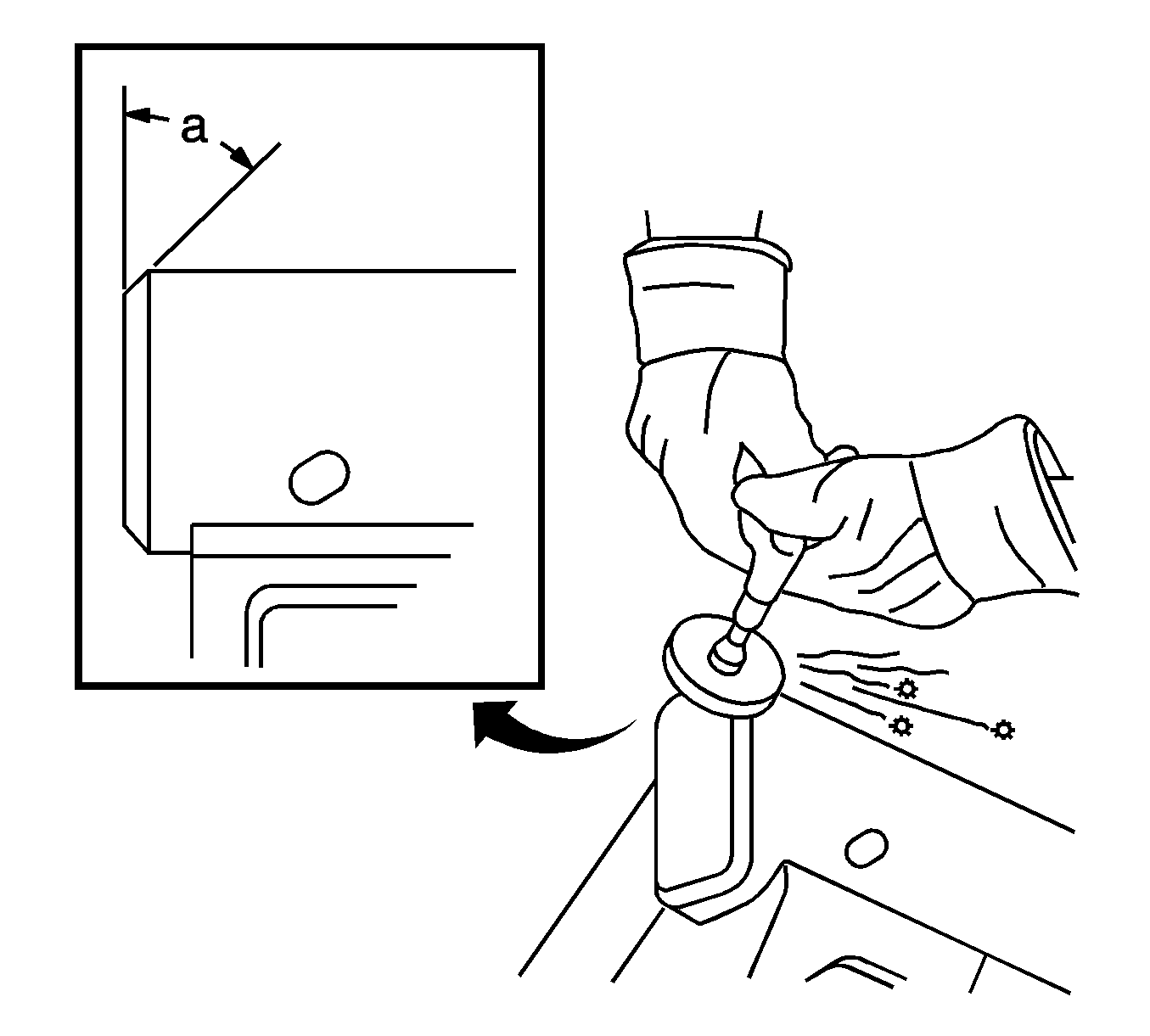
- Grind the existing frame rail seam to taper seam at a 45 degree angle.
- Prepare all of the attaching surfaces as necessary.
- Apply the weld-thru primer to all of the welded surfaces.
- Position the service frame section to the existing frame and clamp in place.
- Continuous-weld the upper and lower horizontal joints threw each corner.
- Continuous-weld the inner and outer vertical joints from corner to corner.
- Clean and prepare all of the welded surfaces.
- Install all of the related panels and components.
- Connect the negative battery cable. Refer to Battery Negative Cable Disconnection and Connection.
- Enable the SIR system. Refer to SIR Disabling and Enabling.
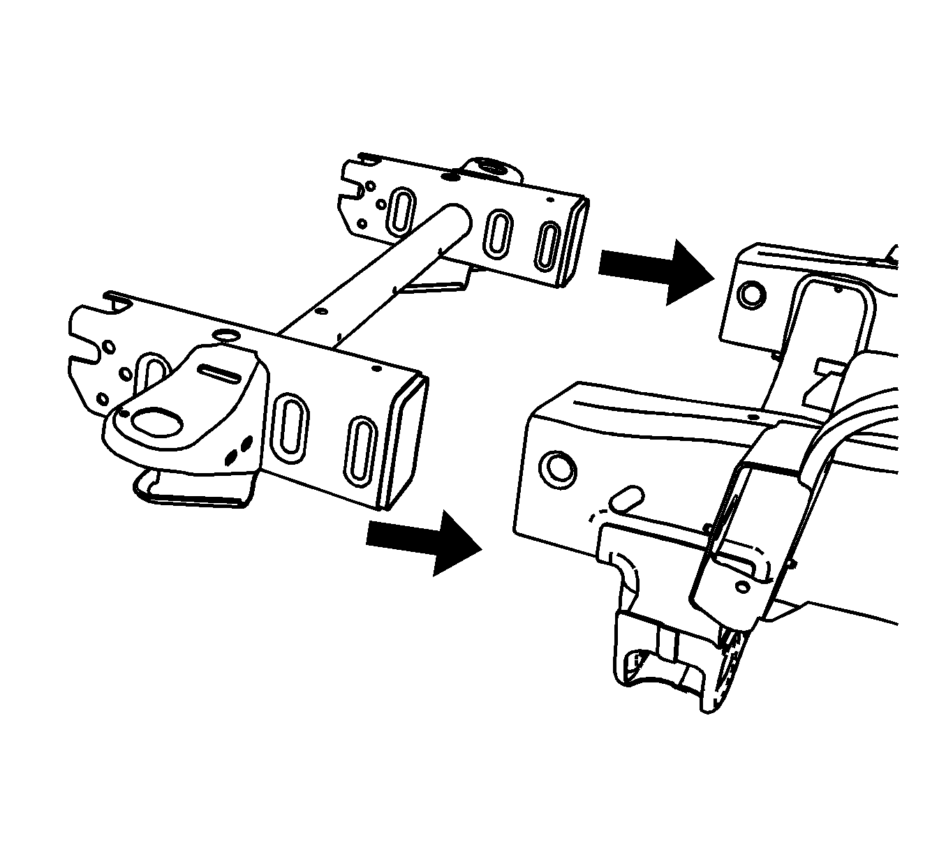
Note: Verify the frame measurements 3-dimensionally to ensure proper position of the service frame.
