Exhaust Manifold Replacement - Left Side 4.8L, 5.3L, 6.0L, and 6.2L
Tools Required
J 42640 Steering Column Anti-Rotation Pin
Removal Procedure
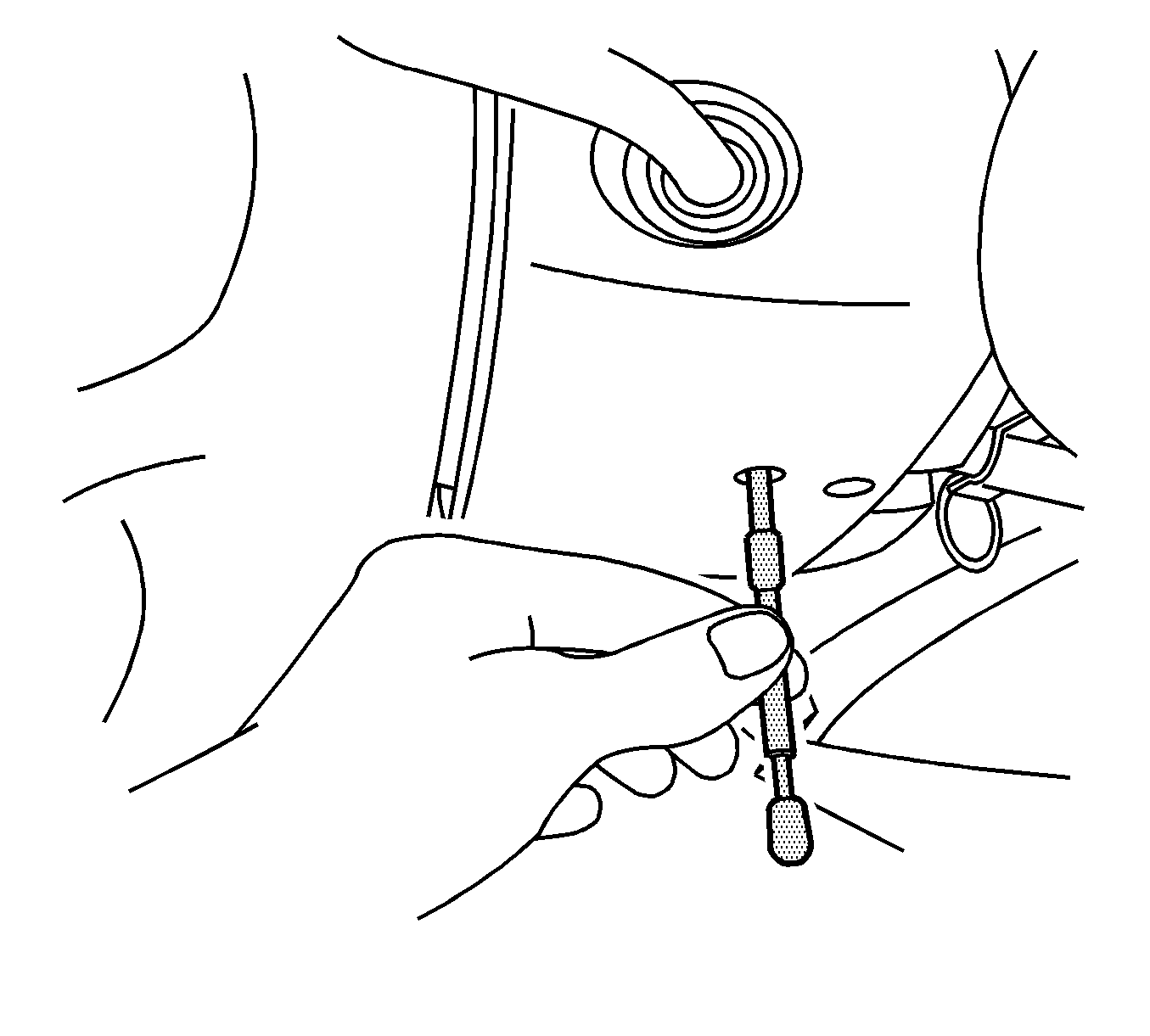
- Install the J 42640 into the steering column lower access hole.
- Remove the left wheelhouse liner. Refer to Front Wheelhouse Liner Replacement - Left Side .
- Fully raise and support the vehicle. Refer to Lifting and Jacking the Vehicle .
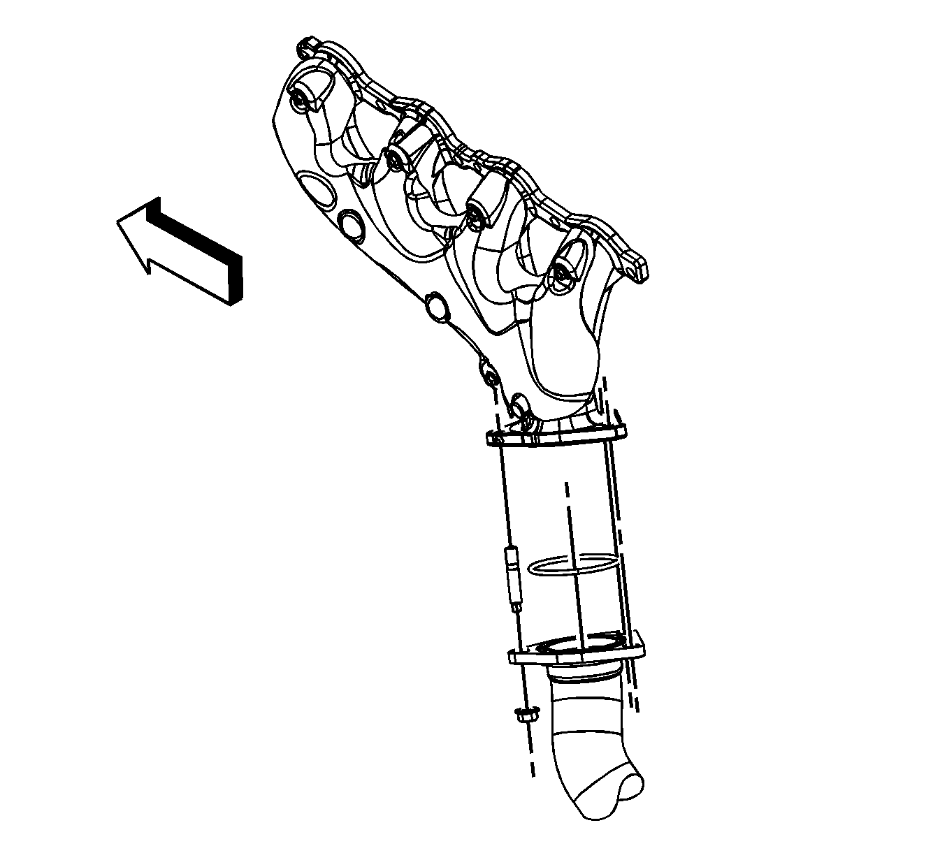
- Remove the catalytic converter to exhaust manifold nuts. (1500 series shown, 2500 series similar).
- Lower the vehicle part way in order to work through the wheel opening.
- Remove the spark plug wires from the spark plugs.
- Remove the spark plug wires from the ignition coils.
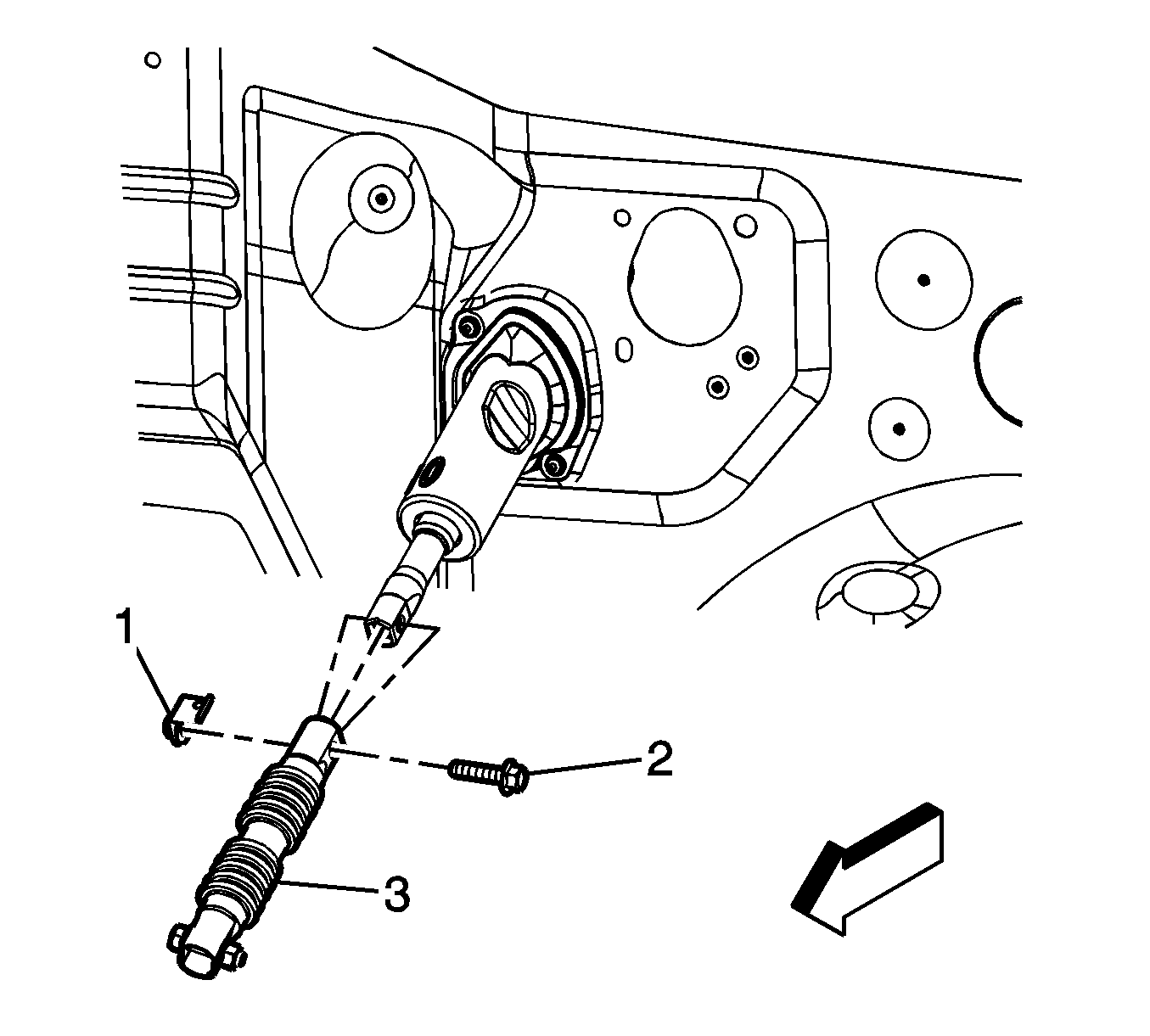
- Mark the relationship of the upper intermediate steering shaft to the steering column.
- Remove the steering shaft coupling bolt (2) and nut (1) from the upper intermediate steering shaft.
- Separate the upper intermediate steering shaft (3) from the steering column, position both shafts out of the way.
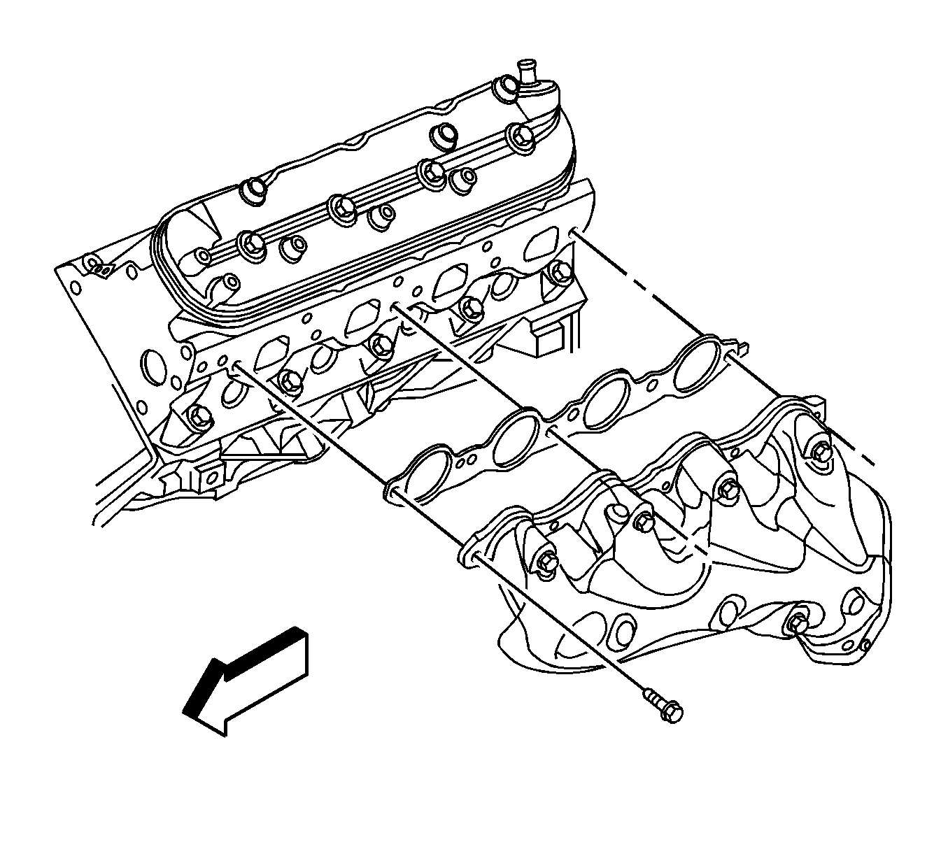
- Remove the exhaust manifold bolts, and exhaust manifold.
- Remove and discard the exhaust manifold gasket.
- Remove and discard the catalytic converter seal.
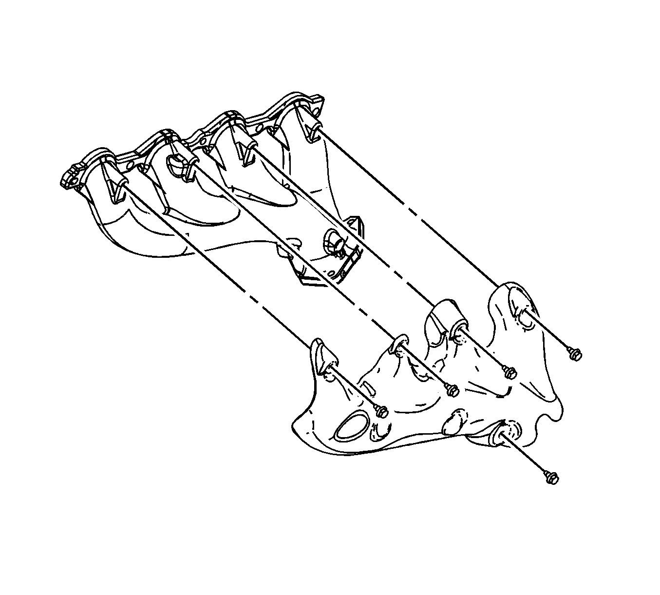
- If replacing the exhaust manifold, remove the exhaust manifold heat shield bolts, and shield from the exhaust manifold.
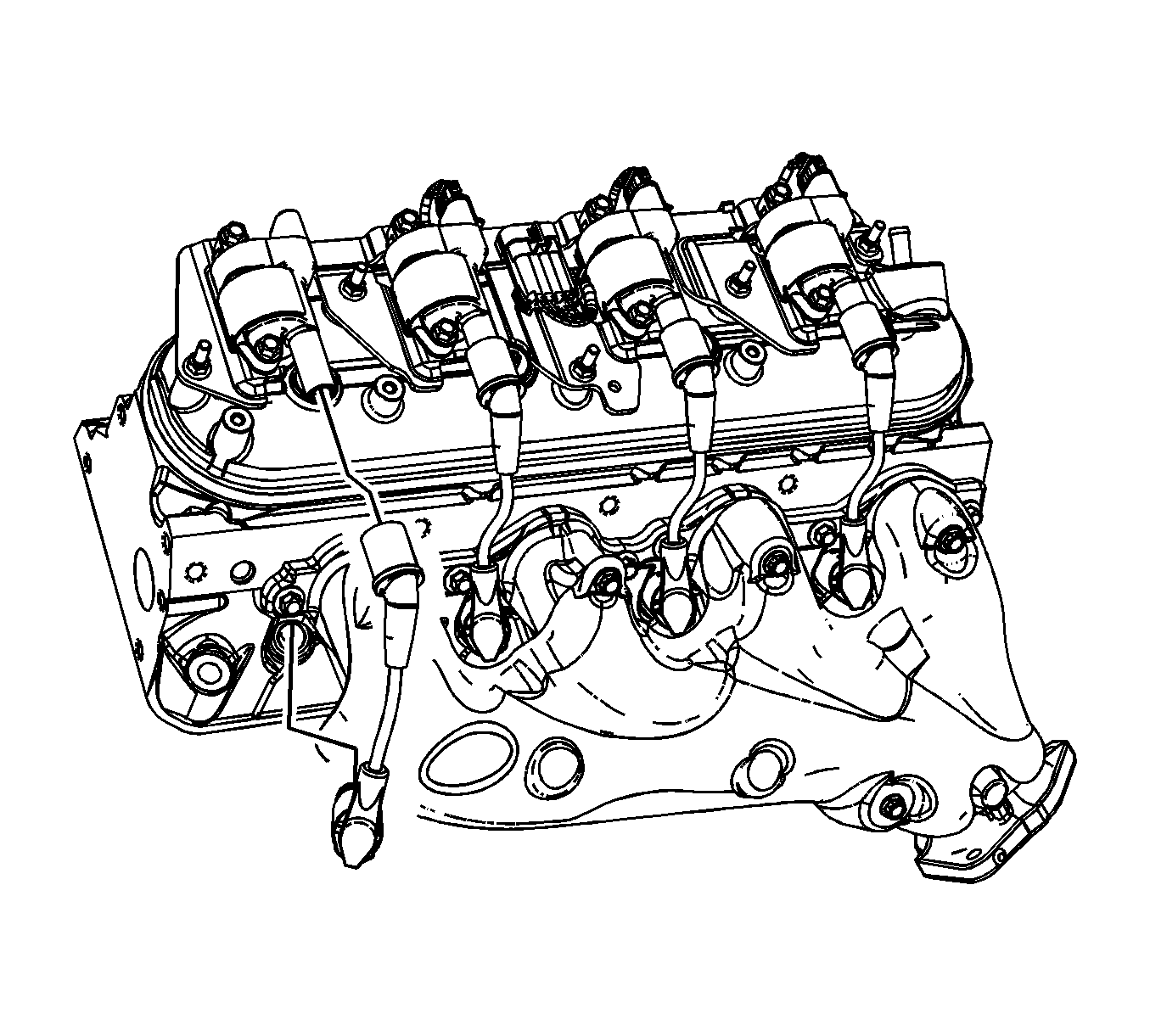
| 6.1. | Twist the spark plug wire boot a 1/2 turn. |
| 6.2. | Pull only on the boot in order to remove the wire from the spark plug. |
| 7.1. | Twist the spark plug wire boot a 1/2 turn. |
| 7.2. | Pull only on the boot in order to remove the wire from the ignition coil. |
Installation Procedure
Important:
• Tighten the exhaust manifold bolts as specified in the service procedure. Improperly installed and/or leaking exhaust manifold gaskets may affect vehicle emissions and/or On-Board Diagnostic (OBD) II system performance. • The cylinder head exhaust manifold bolt hole threads must be clean and free of debris or threadlocking material. • Do not apply sealant to the first 3 threads of the bolt.
- If the exhaust manifold was replaced, position and install the exhaust manifold heat shield, and bolts to the exhaust manifold.
- Clean the threads of the exhaust manifold bolts.
- Apply a 5 mm (0.2 in) wide band of threadlock GM P/N 12345493 (Canadian P/N 10953488), or equivalent to the threads of the exhaust manifold bolts.
- Install a NEW catalytic converter seal to the catalytic converter.
- Position the NEW exhaust manifold gasket and exhaust manifold to the cylinder head.
- Ensure that the exhaust manifold is seated to the catalytic converter.
- Install the exhaust manifold bolts.
- Tighten the bolts a first pass to 15 N·m (11 lb ft). Tighten the exhaust manifold bolts beginning with the center 2 bolts. Alternate from side-to-side, and work toward the outside bolts.
- Tighten the bolts a final pass to 20 N·m (15 lb ft). Tighten the exhaust manifold bolts beginning with the center 2 bolts. Alternate from side-to-side, and work toward the outside bolts.
- Using a flat punch, bend the gasket tab at the rear of the gasket around the cylinder head edge.
- Position and align the marks on the upper intermediate steering shaft and the steering column.
- Install the upper intermediate steering shaft (3) to the steering column.
- Install the steering shaft coupling bolt (2) and nut (1) to the upper intermediate steering shaft.
- Install the spark plug wires to the spark plugs.
- Install the spark plug wires to the ignition coils.
- Inspect the spark plug wires for proper installation.
- Fully raise and support the vehicle.
- Install the catalytic converter to exhaust manifold nuts. (1500 series shown, 2500 series similar).
- Partially lower the vehicle.
- Install the left wheelhouse liner. Refer to Front Wheelhouse Liner Replacement - Left Side .
- Remove the J 42640 from the steering column lower access hole.
Notice: Refer to Fastener Notice in the Preface section.

Tighten
Tighten the bolts to 9 N·m (80 lb in).

Tighten

Tighten
Tighten the bolt/nut to 50 N·m (37 lb ft).

| 14.1. | Push sideways on each boot in order to inspect the seating. |
| 14.2. | Reinstall any loose boot. |

Tighten
Tighten the nuts to 50 N·m (37 lb ft).

Exhaust Manifold Replacement - Left Side 6.6L
Removal Procedure
- Remove the charge air cooler inlet pipe. Refer to Charge Air Cooler Inlet Pipe Replacement.
- Remove the wheelhouse liner. Refer to Front Wheelhouse Liner Replacement - Right Side.
- Perform the following steps working through the wheelhouse opening.
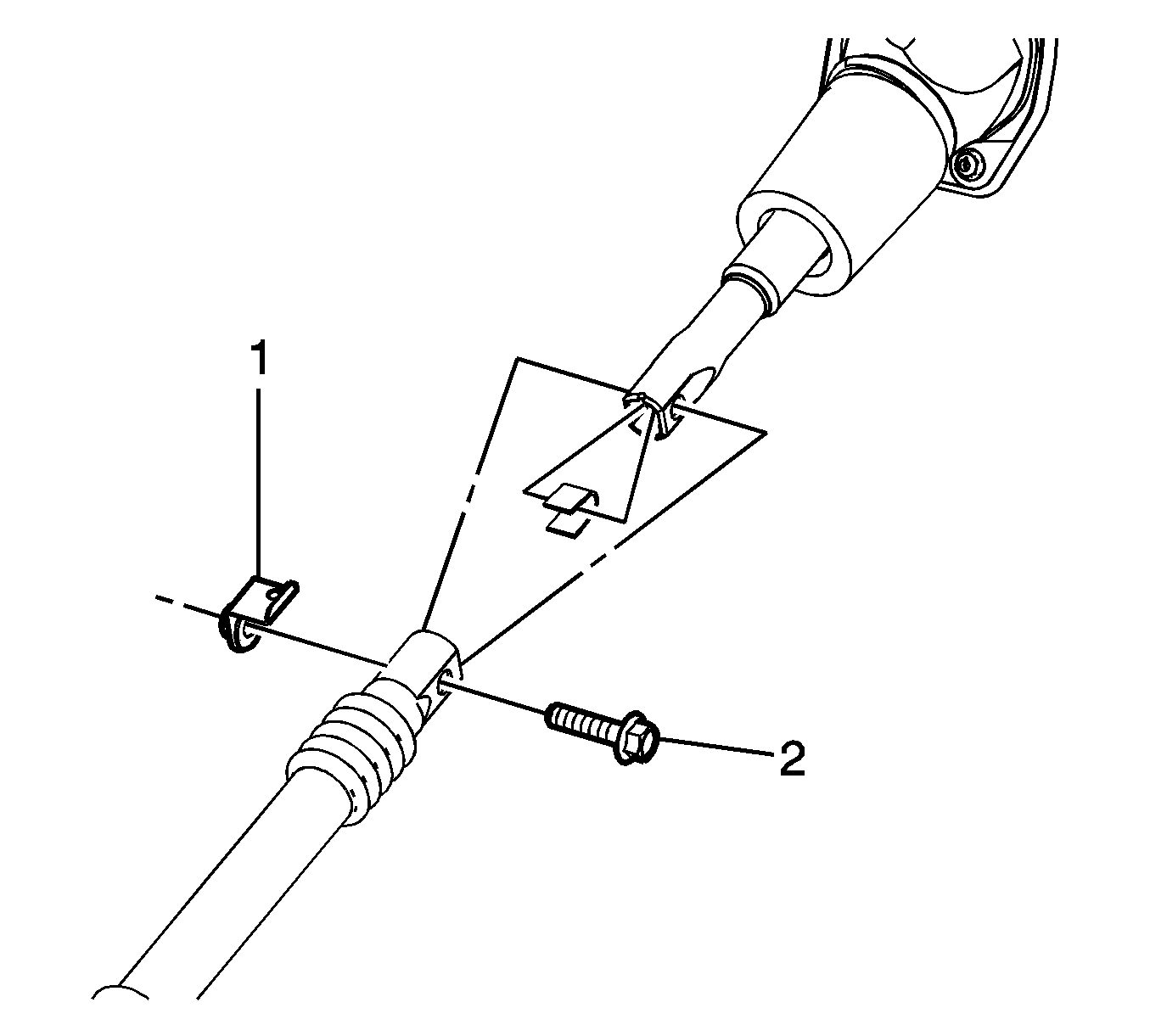
- Remove the steering coupling nut (1) and bolt (2) at the upper intermediate steering shaft.
- Separate the steering shaft coupling from the intermediate shaft.
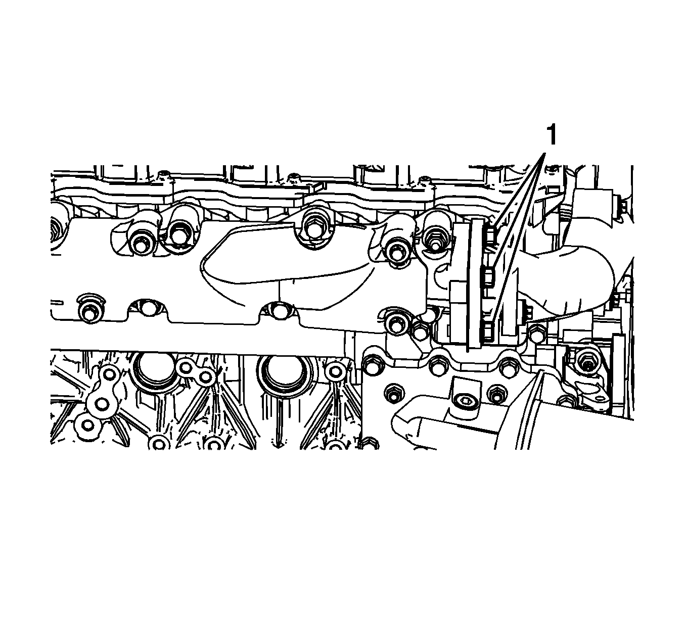
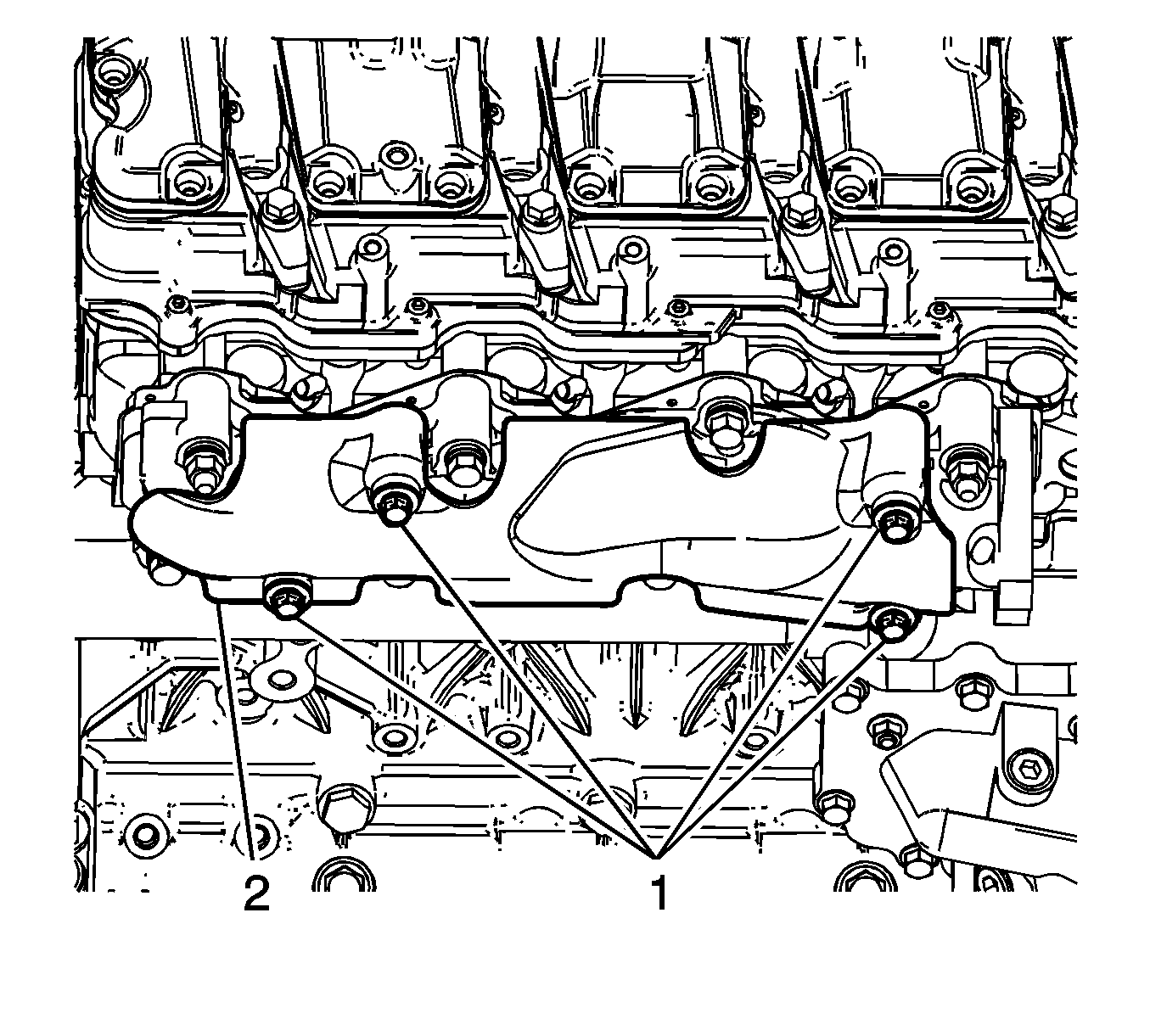
- Remove the exhaust pipe to exhaust manifold bolts (1).
- Remove the exhaust manifold heat shield bolts (1) and shield (2).
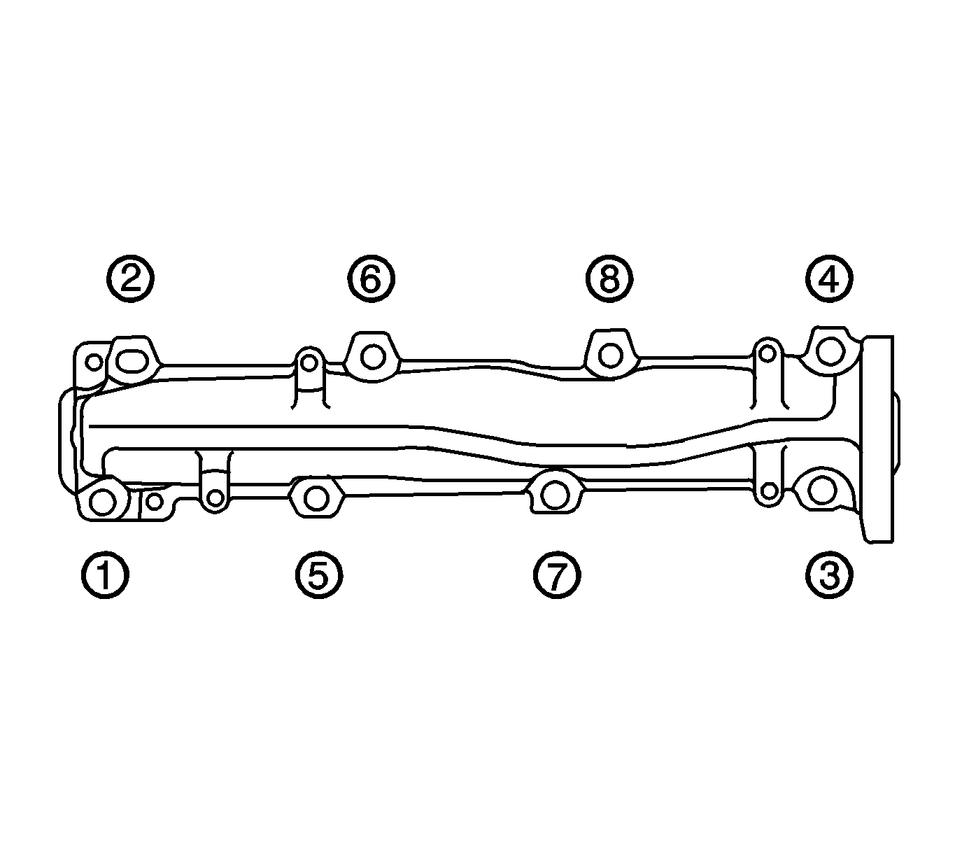
- Remove the exhaust manifold bolts and nuts in the sequence shown.
- Remove the exhaust manifold and gasket. Discard the gasket.
Installation Procedure
- Install the a NEW exhaust manifold gasket onto the manifold studs.
- Position a NEW exhaust pipe gasket between the exhaust manifold and exhaust pipe. Align the tab on the gasket to face outward.
- Install the exhaust manifold onto the studs.
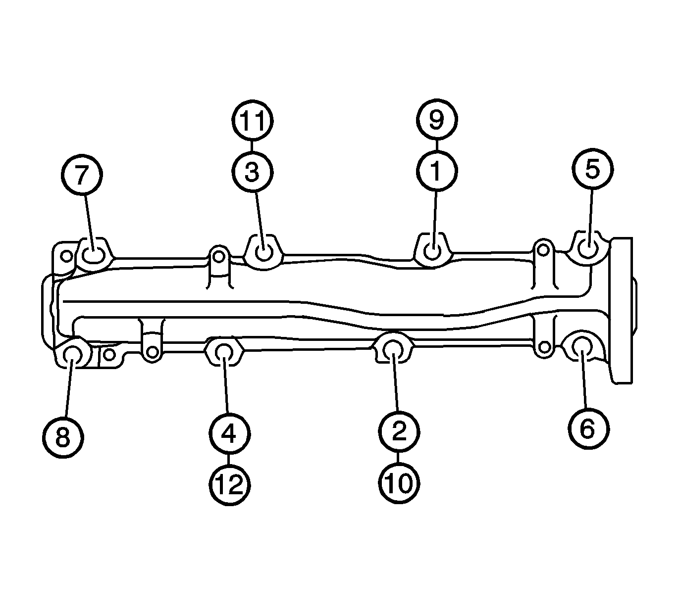
- Install and tighten the exhaust manifold bolts and nuts in the sequence shown.
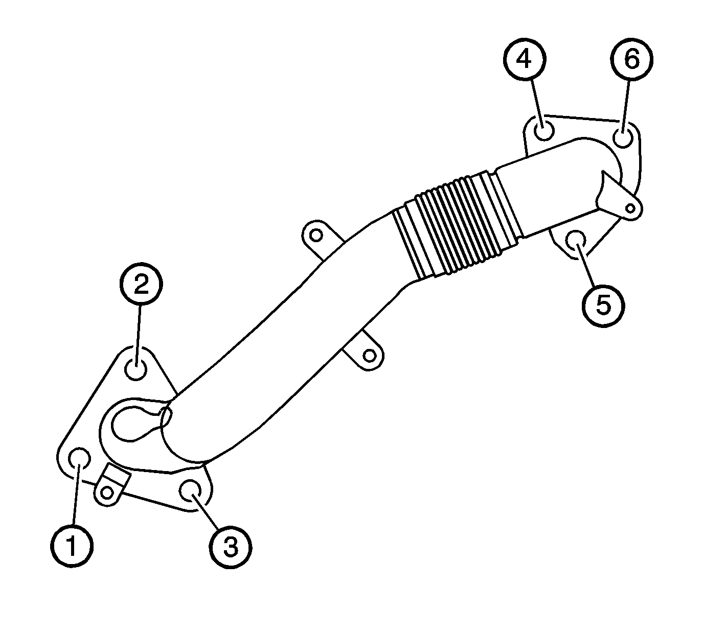
- Install and tighten the exhaust pipe to exhaust manifold bolts in the sequence shown (1, 2, and 3).
- Position the exhaust manifold heat shield (2) to the manifold and install the bolts (1).
- Install the steering shaft coupling to the intermediate shaft.
- Install the steering shaft coupling nut (1) abd bolt (2) at the steering shaft coupling.
- Install the wheelhouse liner. Refer to Front Wheelhouse Liner Replacement - Right Side.
- Remove the charge air cooler inlet pipe. Refer to Charge Air Cooler Inlet Pipe Replacement.
- Lower the vehicle.
Notice: Refer to Fastener Notice in the Preface section.
Tighten
| • | Tighten the bolts/nuts to 57 N·m (42 lb ft). |
| • | Tighten the 4 center bolts/nuts an additional pass to 57 N·m (42 lb ft). |
Tighten
Tighten the bolts to 53 N·m (39 lb ft).

Tighten
Tighten the bolts to 10 N·m (89 lb in).

Tighten
Tighten the nut and bolt to 50 N·m (37 lb in).
Exhaust Manifold Replacement - Left Side 4.3L
Removal Procedure
- Raise and suitably support the vehicle. Refer to Lifting and Jacking the Vehicle .
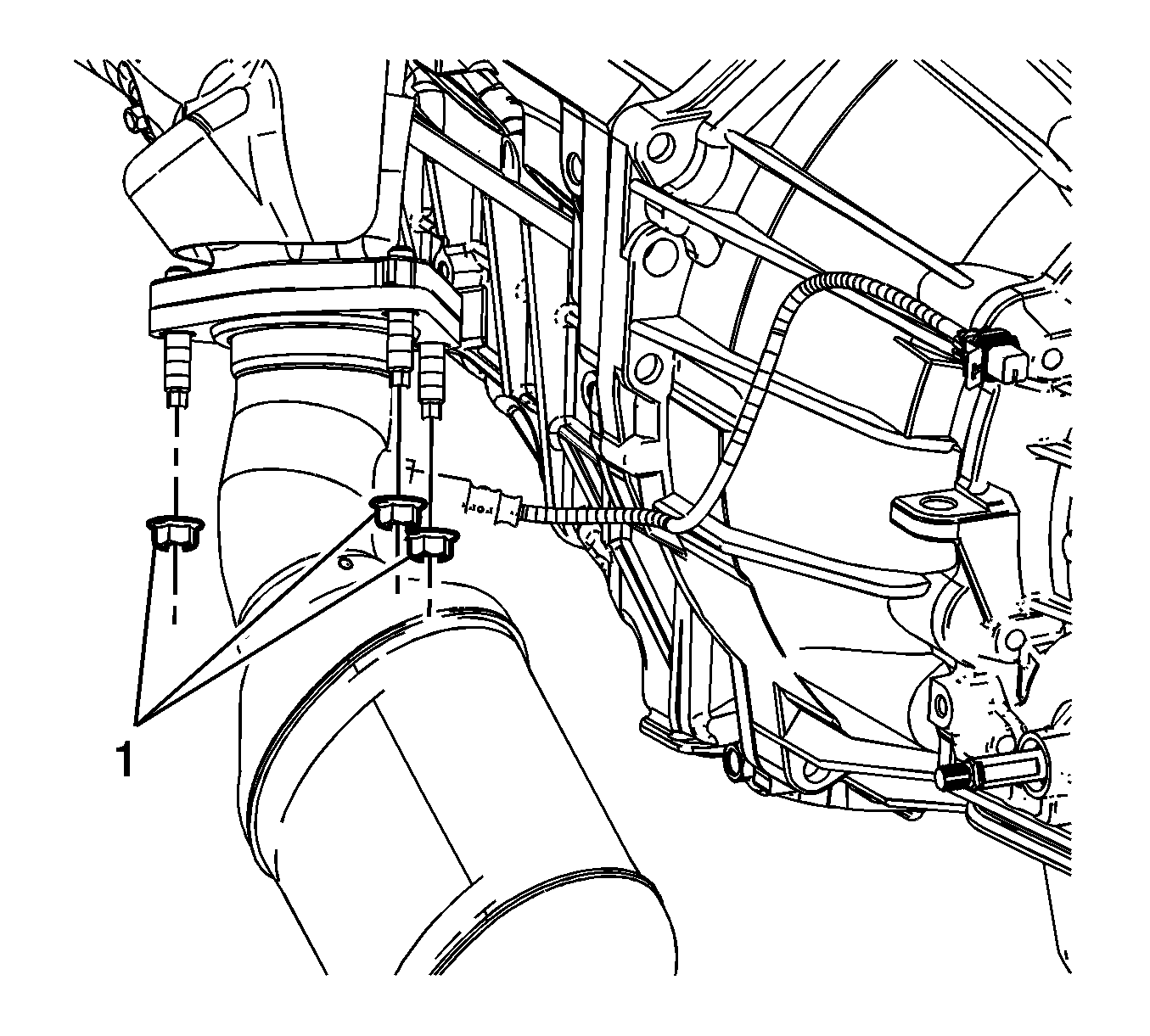
- Remove the catalytic converter to exhaust manifold nuts (1).
- Lower the vehicle.
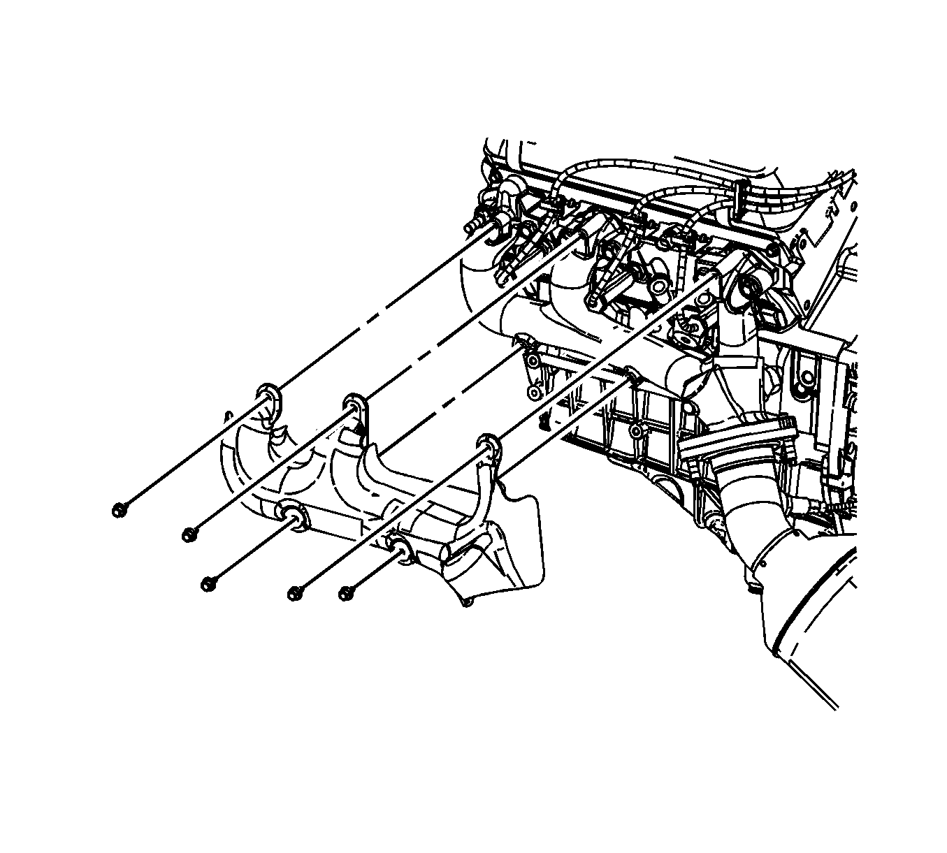
- Remove the exhaust manifold heat shield bolts and shield.
- Remove the spark plugs. Refer to Spark Plug Replacement .
- Reposition the spark plug wires out of the way, if necessary.
- Remove the exhaust manifold bolts and stud.
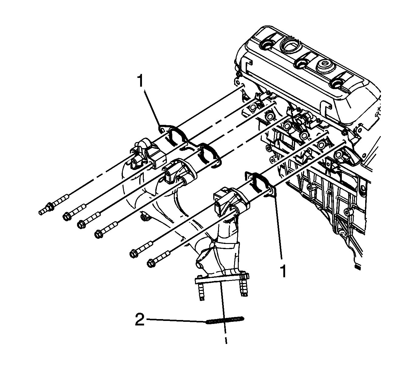
- Remove the exhaust manifold and gaskets (1). Discard the gaskets.
- Remove the exhaust manifold to catalytic converter seal (2). Discard the seal.
Installation Procedure
- Install a NEW exhaust manifold to catalytic converter seal (2) into the relief in the catalytic converter.
- Place the exhaust manifold into position and install the manifold studs to the catalytic converter.
- Place the NEW exhaust manifold gaskets (1) between the manifold and the cylinder head.
- Install the exhaust manifold bolts and stud.
- Install the spark plugs. Refer to Spark Plug Replacement .
- Position the exhaust manifold heat shield to the manifold and install the bolts.
- Raise and support the vehicle.
- Install the catalytic converter to exhaust manifold nuts (1).
- Lower the vehicle.

Notice: Refer to Fastener Notice in the Preface section.
Tighten
Tighten the bolts/stud to 30 N·m (22 lb ft).

Tighten
Tighten the bolts to 9 N·m (80 lb in).

Tighten
Tighten the nuts to 50 N·m (37 lb ft).
