Transfer Case Shift Control Switch
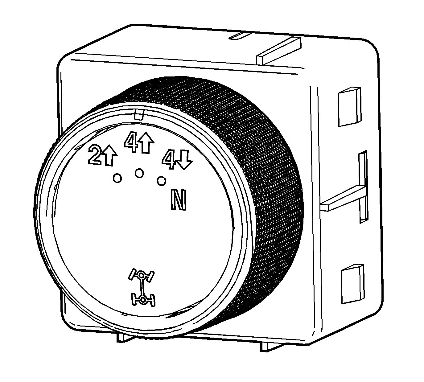
The Magna Powertrain (MP) 1625/1626 RPO NQF transfer case features a 3 mode shift control switch located on the instrument panel. When the ignition is in the RUN position, the transfer case shift control module monitors the transfer case shift control switch to determine if the driver desires a new mode/range position. At a turn of the transfer case shift control switch, the lamp of the new desired position will begin flashing to inform the driver that the transfer case shift control module has received the request for a new mode/range position. The lamp continues to flash until all shifting criteria has been met and the new mode/range position has been engaged. Once the new mode/range position is fully active, the switch indicator for the new position will remain ON constantly. In the event that the transfer case shift control module can not or will not complete the shift, the indicator returns to the previously selected position; this is a Transfer Case Shift Control Switch Indicator Flashes, then Returns to Previous Mode condition.
The MP 1625/1626 transfer case provides the driver with 4 manual mode/range positions:
| • | 2HI - 2 Wheel Drive high range |
| • | 4HI - 4 Wheel Drive high range |
| • | 4LO - 4 Wheel Drive low range, 2.68:1 gear ratio reduction |
| • | NEUTRAL |
The driver may choose to select any of these mode/range positions while driving the vehicle. However, the transfer case will not allow a shift into or out of 4LO unless the following criteria has been met:
| • | The ignition switch is in RUN. |
| • | The automatic transmission is in NEUTRAL. |
| • | The vehicle speed is below 5 km/h (3 mph). |
This transfer case also has a NEUTRAL position. A shift to the NEUTRAL position allows the vehicle to be towed without rotating the transmission output shaft. NEUTRAL position may be obtained only if the following criteria has been met:
| • | The ignition switch is in RUN. |
| • | The automatic transmission is in NEUTRAL. |
| • | The vehicle speed is below 5 km/h (3 mph). |
| • | The transfer case is in 2HI mode. |
Once these conditions have been met, turn the rotary switch clockwise past 4 low and hold for 10 seconds. When the system completes the shift to NEUTRAL, the red NEUTRAL lamp will illuminate.
A shift to the NEUTRAL position allows the vehicle to be towed without rotating the transmission output shaft. In the NEUTRAL position, the rear propeller shaft rotates the transfer case rear output shaft, in turn rotating the oil pump, thus providing constant lubrication during towing. This NEUTRAL position is a 4WD NEUTRAL, meaning the front and rear outputs of the transfer case are engaged as though in 4HI. With a disengaged front axle, there is no power flow to the front wheels, thus allowing towing with the front wheels off the ground or flat towing without driveline binding.
The NQF transfer case is available in 2 variations, depending on the engine and transmission configurations. The variations allow the transfer case to handle different torque loads. When servicing the transfer case, it is important to understand which variation is being serviced because of the difference in parts.
Model | Transmission | Input Shaft | Output Shaft | Chain Size | Chain Series | Hi/Low Planetary | Application |
|---|---|---|---|---|---|---|---|
MP 1625 Heavy Duty (HD) | MYD - 6L90 | 29T Spline | 31T Spline | 7/16 X 1.5 in | 9600 Series Rocker Pin Chain | 5 Pinion | K2 |
MP 1626 Super Heavy Duty (SHD) | MYD - 6L90 MW7 - Allison | 29T Spline | 31T Spline | 7/16 X 1.5 in | 2300 Series Round Pin Chain | 5 Pinion | K2, K3 |
All Canadian MP1625 Transfer Cases will be equipped with the 2300 series round pin chain.
Additional differences in these models are listed below:
| • | MP1625: The input shaft seal is a single lip seal used only with dry cavity adapters |
| • | MP1626: The input shaft seal is a dual lip seal used specifically for the MW7 which has a wet cavity adapter. These seals are also used for the MYD in order to retain a common part number for this model. |
2WD Mode Power Flow
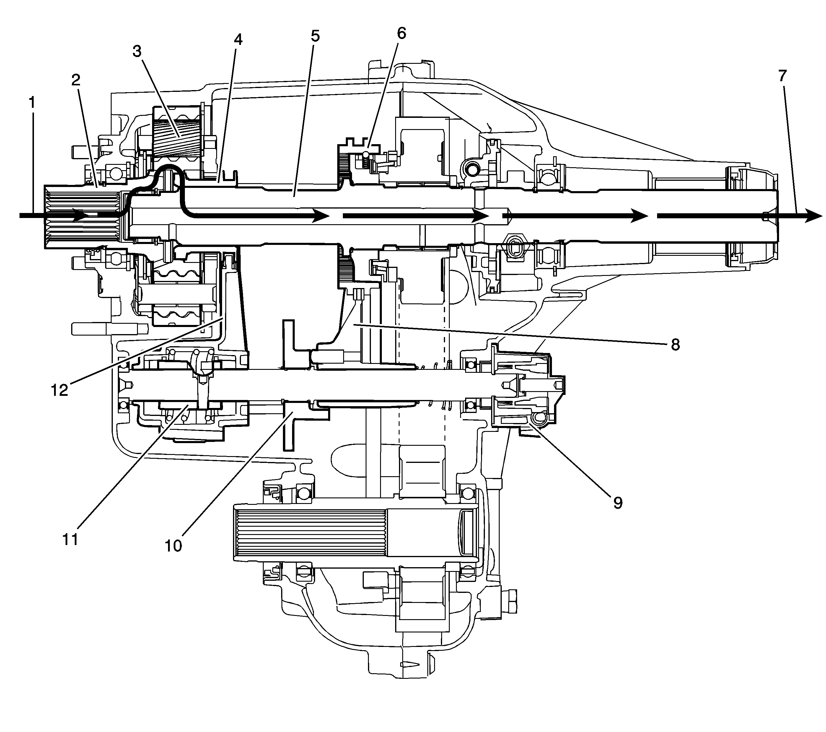
The transfer case is shifted by an encoder motor (9) on the control actuator shaft. The control actuator shaft rotates the 2/4 wheel drive actuator cam (10) and moves the high/low range shift fork (12) or the 2/4 wheel drive mode shift fork (8). Depending on the selected mode or range, the shift forks move either the high/low clutch (4) for the high/low range planetary assembly (3) or the synchronizer sleeve (6) for the 2/4 wheel drive mode. In 2WD mode, the engine power from the transmission (1) is delivered to the input shaft (2). The engagement teeth on the inside of the input shaft (2) are engaged to the outer teeth on the high/low clutch (4). The high/low clutch (4) is slip splined to rear output shaft (5). The engine power flows from the high/low clutch (4) to the rear output shaft (5) and delivered to rear propeller shaft (7).
4HI Mode Power Flow
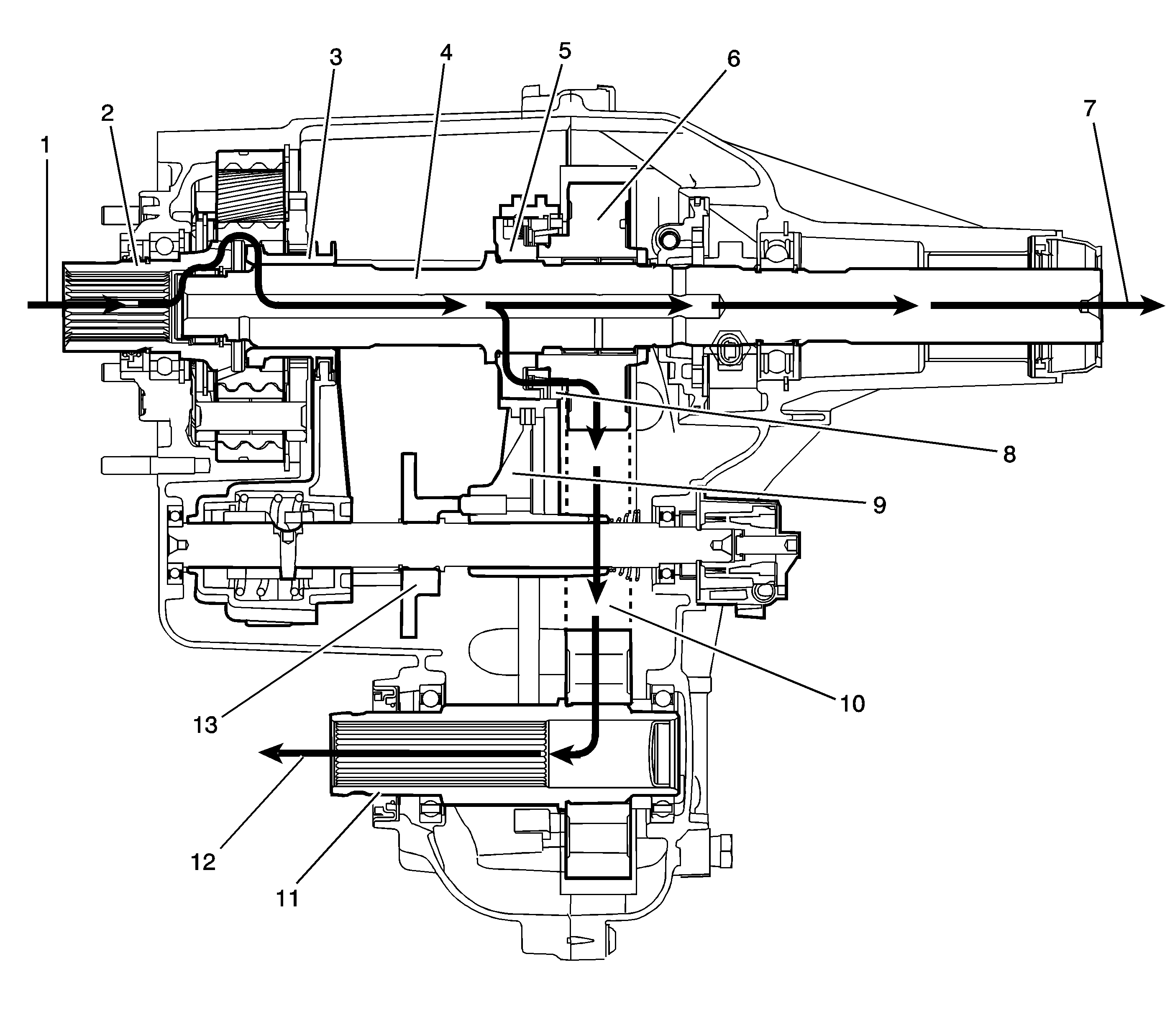
In 4HI mode, the engine power from the transmission (1) is delivered to the input shaft (2). The engagement teeth on the inside of the input shaft (2) are engaged to the outer teeth on the high/low clutch (3). The high/low clutch (3) is slip splined to the rear output shaft (4). During a shift mode from 2HI to 4HI, the cam profile on the 2/4 wheel drive actuator cam (13) pushes the 2/4 wheel drive mode shift fork (9) and the synchronizer sleeve. The sleeve, engaging the synchronizer (8), equalizes the front propeller shaft (12) and rear propeller shaft (7) speeds. The sleeve then engages to the drive sprocket (6). The engine power flow for driving the front propeller shaft (12), now travels from the rear output shaft (4) to the synchronizer hub (5), which is splined to the rear output shaft (4). The power flows from the synchronizer hub (5) to the sleeve and then to the drive sprocket (6). The power flow is transmitted by a chain (10) to the driven sprocket on the front output shaft (11) and to the front propeller shaft (12). The front and rear propeller shafts are being driven at equal RPM, therefore giving a four wheel drive mode. This mode should only be used for extra traction. Using this mode on dry pavement causes tire scuffing when turning.
4LO Mode Power Flow
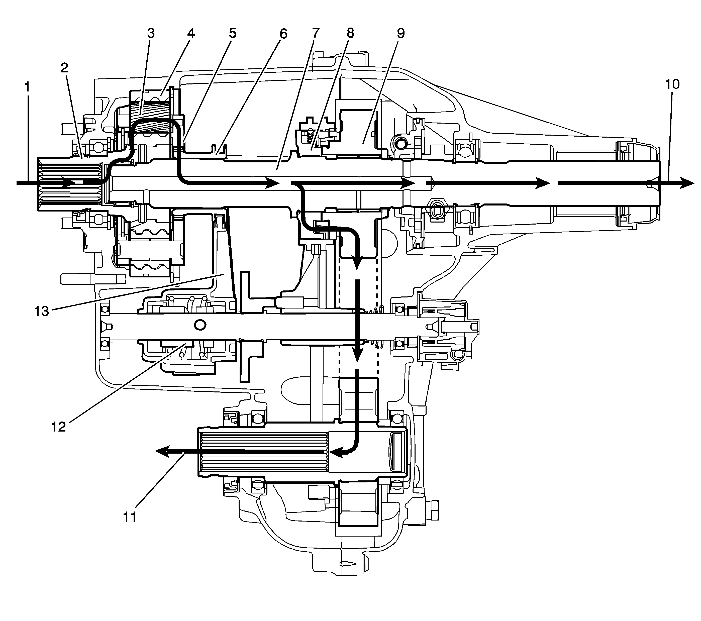
During a range shift request to 4LO, a separate cam profile, in the high/low shift fork spring assembly (12), moves the high/low shift fork (13). The high/low shift fork (13) moves the high/low clutch (6) rearward. The high/low clutch (6) outer teeth disengage from the input shaft (2) high-speed teeth. The high/low clutch (6) outer teeth then engage in the high/low planetary carrier teeth (5). The power flow is now from the transmission (1) to the planetary teeth on the input shaft (2) to the planetary gears (3) in the high/low planetary carrier assembly (5). Rotating the planetary gears (3), which are engaged in the high/low internal gear (4), rotates the high/low planetary carrier assembly (5). The high/low planetary carrier assembly (5) delivers the power to the high/low clutch (6). The high/low clutch (6) then drives the rear output shaft (7), providing a 2.68:1 gear ratio reduction to the rear output shaft (7). The sleeve is still engaged to drive the drive sprocket (9), as in the 4HI position, providing the engine power to the rear propeller shaft (10) and to the front propeller shaft (11).
NEUTRAL Mode Power Flow
Shifting to the NEUTRAL position, the high/low clutch is centered between the input shaft and the high/low planetary carrier. The high/low clutch is not engaged with either the input shaft or the high/low planetary carrier teeth. The 2/4 wheel drive synchronizer is in the 4HI mode position.
Electrical Components
Below is a list of major components that make up the automatic transfer case (ATC) system.
Front Axle Actuator
The front axle actuator engages and disengages the front axle. The front axle actuator consists of a permanent magnetic (PM) motor, a worm gear controlled plunger, a front axle switch and an electronic control circuit. When a range shift to 4HI, or 4LO is requested, the transfer case shift control module requests engagement of the front axle by grounding the axle actuator control circuit through a current limiting driver. The front axle actuator also sends a return signal to the transfer case shift control module indicating when the 4WD is engaged.
SERVICE Indicator (4WD)
The SERVICE indicator (4WD) is an integral part of the cluster and cannot be serviced separately. This indicator is used to inform the driver of malfunctions within the ATC system. The SERVICE indicator (4WD) is controlled by the transfer case shift control module via a Class 2 message or by a service indicator control circuit.
Transfer Case Two/Four Wheel Drive Actuator Assembly
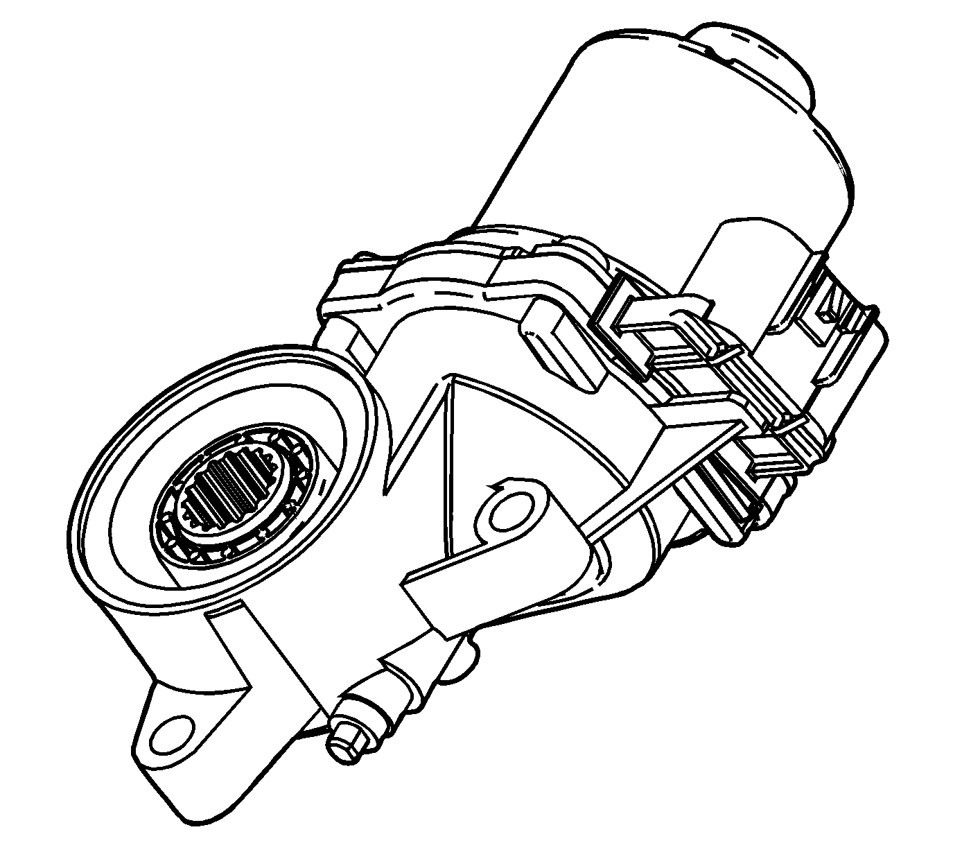
The transfer case two/four wheel drive actuator assembly consists of a PM DC motor and gear reduction assembly. It is located on the left side, drivers side, of the transfer case. When activated, it turns the sector shaft of the transfer case clockwise or counter clockwise to shift the transfer case. The encoder motor is controlled by the transfer case shift control module. This circuit consists of a driver on both the motor control A and motor control B circuits. The encoder motor is bi-directional, to allow the motor to shift the transfer case from 2HI or 4HI to NEUTRAL and 4LO positions. The transfer case encoder motor can be fully driven clockwise or counterclockwise using a scan tool. You may also monitor motor control A and B circuits using a scan tool.
The two/four wheel drive actuator assembly also has a built in incremental sensor. This device is a linear encoder. The transfer case shift control module sends a 5 volt reference signal to the encoder. The transfer case shift control module reads the voltage back based on the exact position of the sector shaft of the transfer case. The transfer case shift control module knows if a shift has been completed and if the shift is somewhere in between.
The encoder motor on the MP 1625/1626 does not have an internal brake like the NVG 246. The encoder motor is not serviceable and must be replaced as an assembly.
Transfer Case Shift Control Module
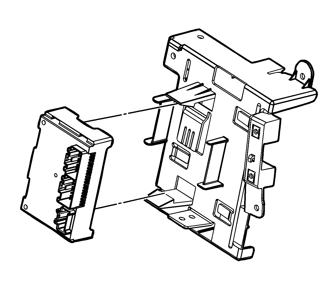
The transfer case shift control module has been standardized for all K trucks. The transfer case shift control module contains the same hardware, boot software, and operational software found in other GM K trucks. The only difference is the calibration file downloaded into the transfer case shift control module memory. The transfer case shift control module comes with the appropriate calibrations out of the factory, but new calibrations must be flashed into the transfer case shift control module during service. This is especially important if a new transfer case shift control module is installed during service. Calibration files may be introduced irregularly. See your technical service bulletins.
Vehicle Speed Sensor (VSS)
There is a VSS mounted to the transfer case on the rear output shaft. The VSS is a PM generator. The PM generator produces a AC voltage. The AC voltage and frequency increases as speed increases. The VSS is an input to the powertrain control module (PCM). The PCM sends this information to the transfer case shift control module via the GM LAN serial data bus.
