For 1990-2009 cars only
Tools Required
KM-507-C Ball Joint Remover
Removal Procedure
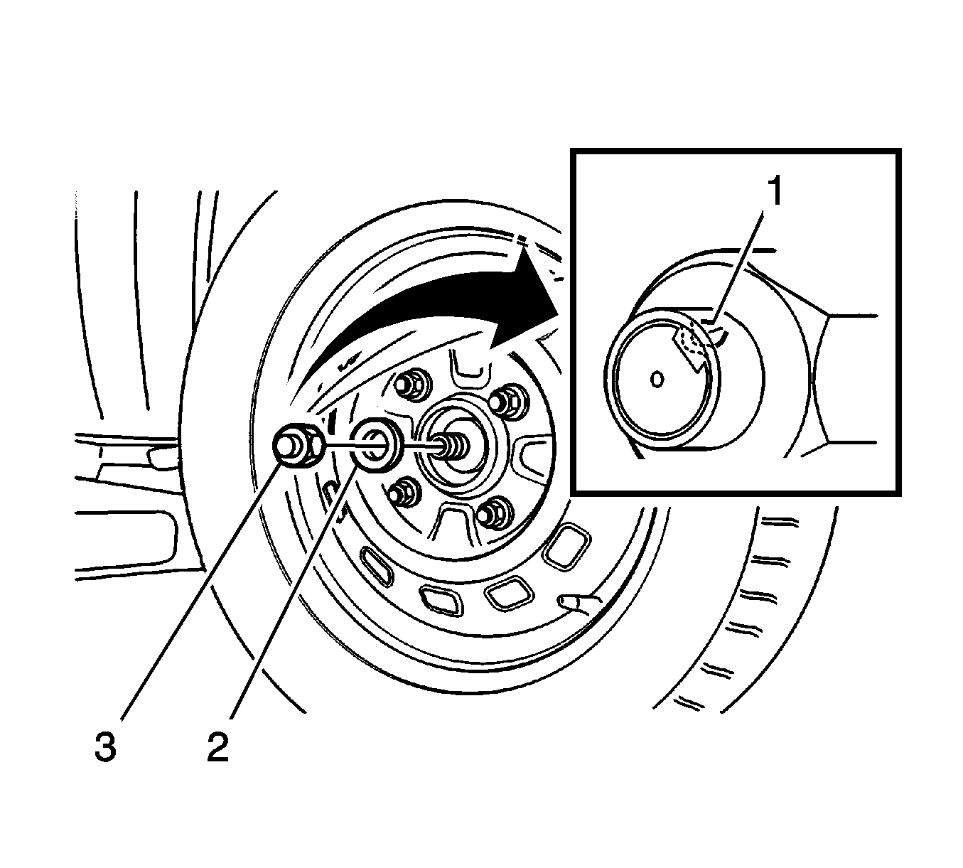
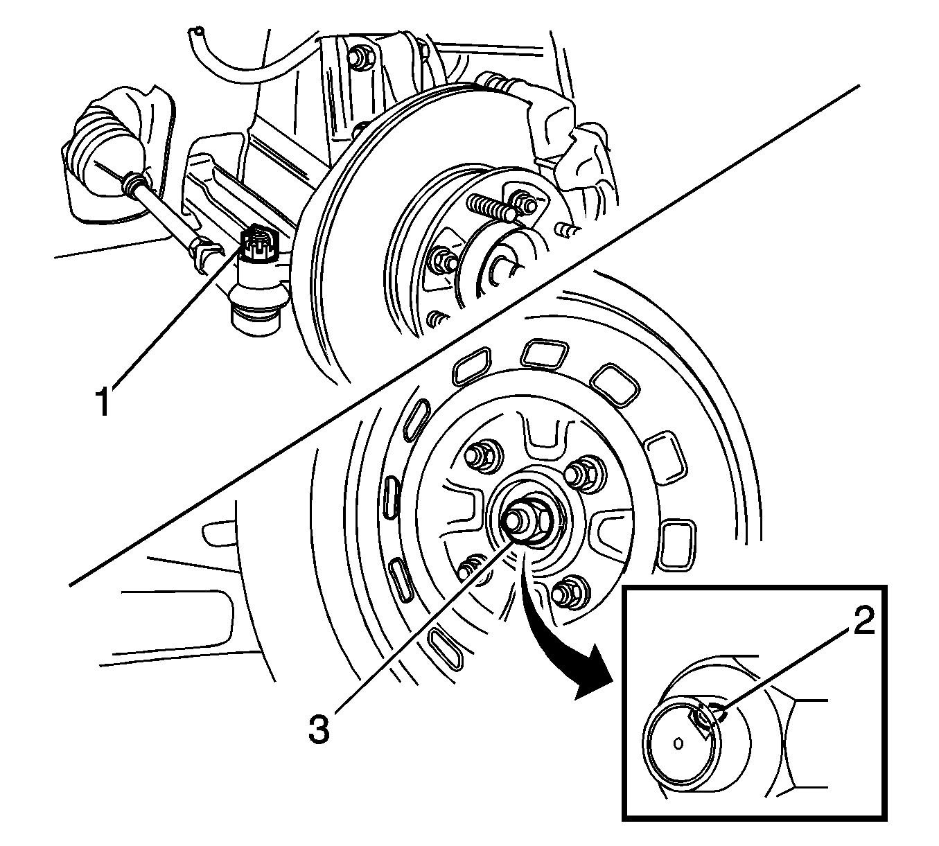
- Straighten the bent flange caulking nut (1).
- Remove the caulking nut (3).
- Remove the washer (2).
- Remove the tire and wheel assembly. Refer to Tire and Wheel Removal and Installation in Tires and Wheels.
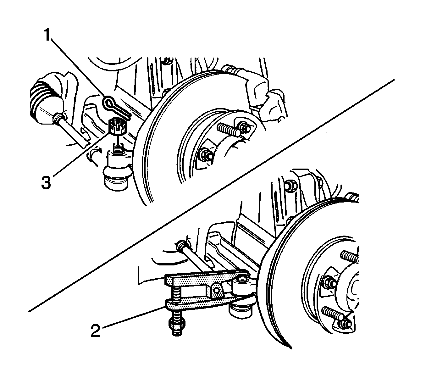
- Remove the cotter pin (1).
- Remove the castellated nut (3).
- Separate the tie rod end from the knuckle assembly using KM-507-C .
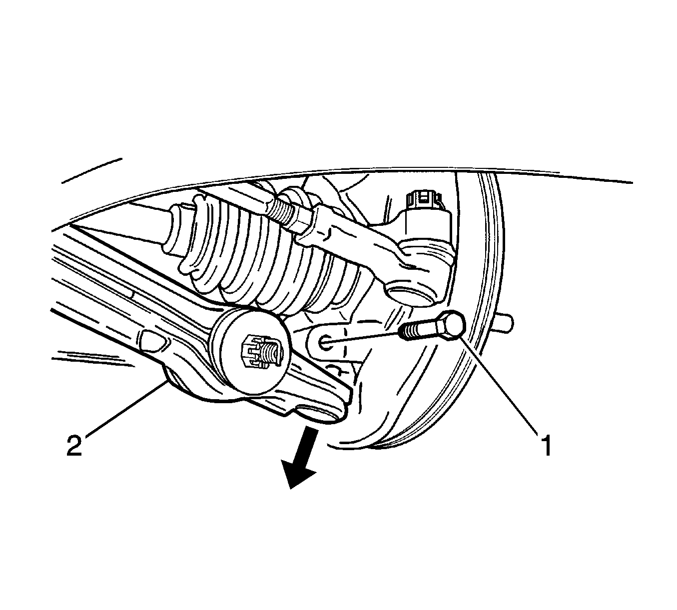
- Remove the stud bolt (1).
- Separate the control arm (2) from the knuckle assembly.
- Remove the brake caliper from the knuckle assembly. Refer to Brake Caliper Replacement in Disc Brakes.
- Remove the ABS wheel speed sensor from the knuckle assembly, if applicable. Refer to Front Wheel Speed Sensor Replacement in Antilock Brake System.
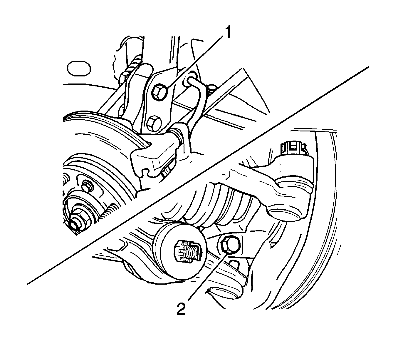
- Remove the strut bracket bolts (1).
- Separate the knuckle assembly from the drive shaft by pulling the steering knuckle assembly.
- Remove the steering knuckle assembly from the vehicle.
Installation Procedure
- Install the steering knuckle assembly in the vehicle with the strut bracket bolts (1).
- Install the ABS wheel speed sensor to the knuckle assembly. Refer to Front Wheel Speed Sensor Replacement in Antilock Brake System.
- Install the brake caliper to the knuckle assembly. Refer to Brake Caliper Replacement in Disc Brakes.
- Install the control arm into the knuckle assembly with the stud bolt (2).
- Install the tie rod end to the knuckle assembly.
- Install the tie rod end-to-knuckle castellated nut (1) and the cotter pin.
- Install the tire and wheel assembly. Refer to Tire and Wheel Removal and Installation in Tires and Wheels.
- Install the washer.
- Install the caulking nut (3).
- Bend the caulking nut flange (2).
Notice: Refer to Fastener Notice in the Preface section.

Tighten
Tighten the strut bracket bolts to 70-90 N·m (52-66 lb ft).
Tighten
Tighten the stud bolt to 50-70 N·m (36-52 lb ft).
Tighten
Tighten the castellated nut to 30-55 N·m (22-41 lb ft).
Tighten
Tighten the caulking nut to 210 N·m (155 lb ft).
