For 1990-2009 cars only
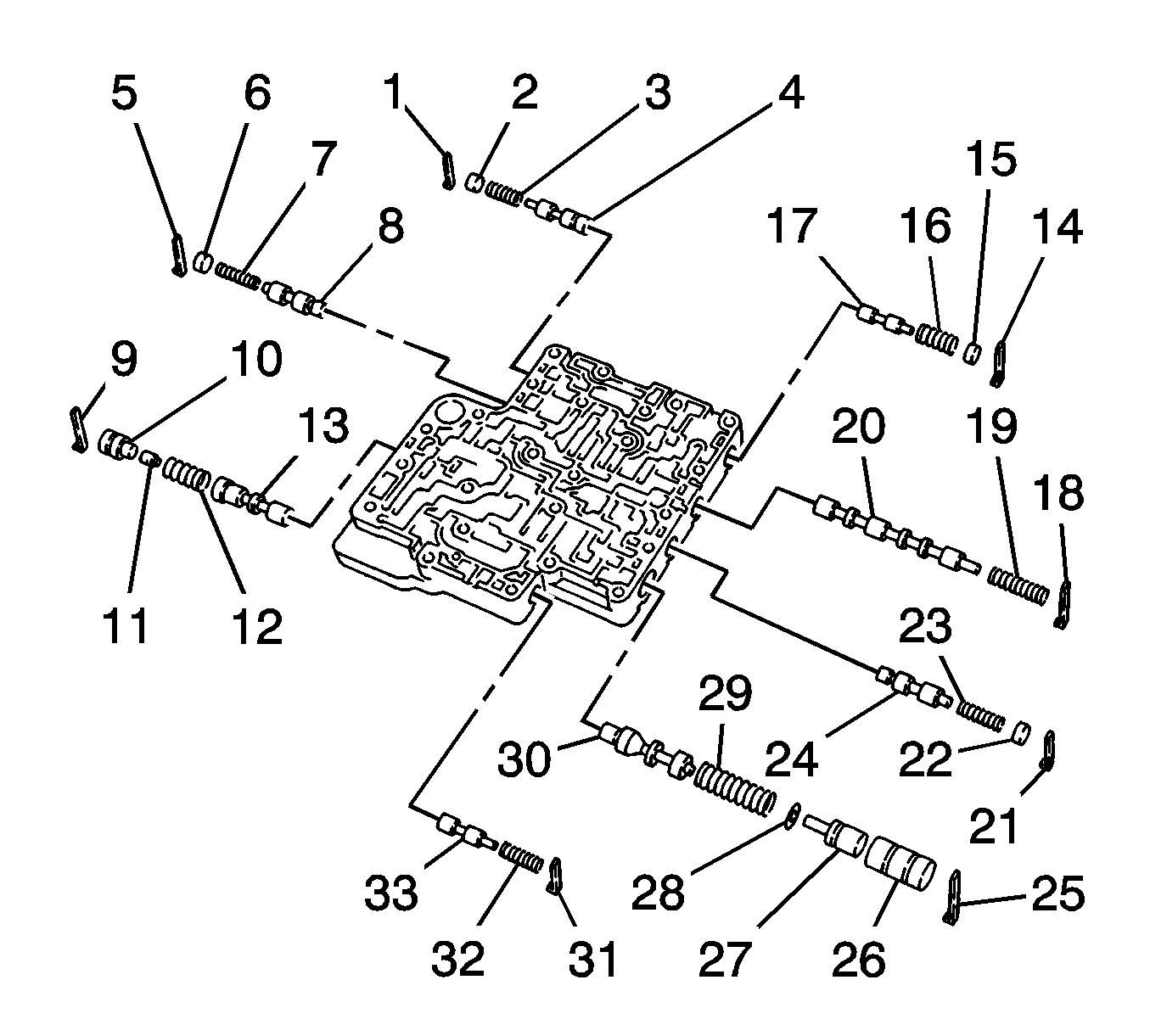
- Remove the retainer plate pin (1), the plug (2), the spring (3) and the 1-2 modulator valve (4).
- Remove retainer plate pin (5), the plug (6), the spring (7) and the neutral control valve (8).
- Remove the retainer plate pin (9), the valve sleeve (10), the valve plug (11), the spring (11), and the lock-up control valve (13).
- Remove the retainer plate pin (14), the plug (15), the spring (16) and the servo release timing valve (17).
- Remove the retainer plate pin (18), the spring (19) and the shift valve B (20).
- Remove the retainer plate pin (21), the plug (22) the spring (23) and the accumulator control valve (24).
- Remove the retainer plate pin (25), the valve sleeve (26), the valve plug (27), the spring seat (28), the spring (29) and the pressure regulator valve (30).
- Remove the retainer plate pin (31), the spring (32) and the pilot valve (33).

Important:
• Each valve can be removed by being slid with the weight of the valve itself. • If the valve will not slide in this manner, push it out with a wire or
face the valve inserting side downward and tap the valve lightly with rubber-headed
hammer. Do not scratch the valve and damage its surface or hole. • Do not use a magnet. It may cause residual magnetism. • Be careful not to drop or lose the valve and internal components.
Check Procedure
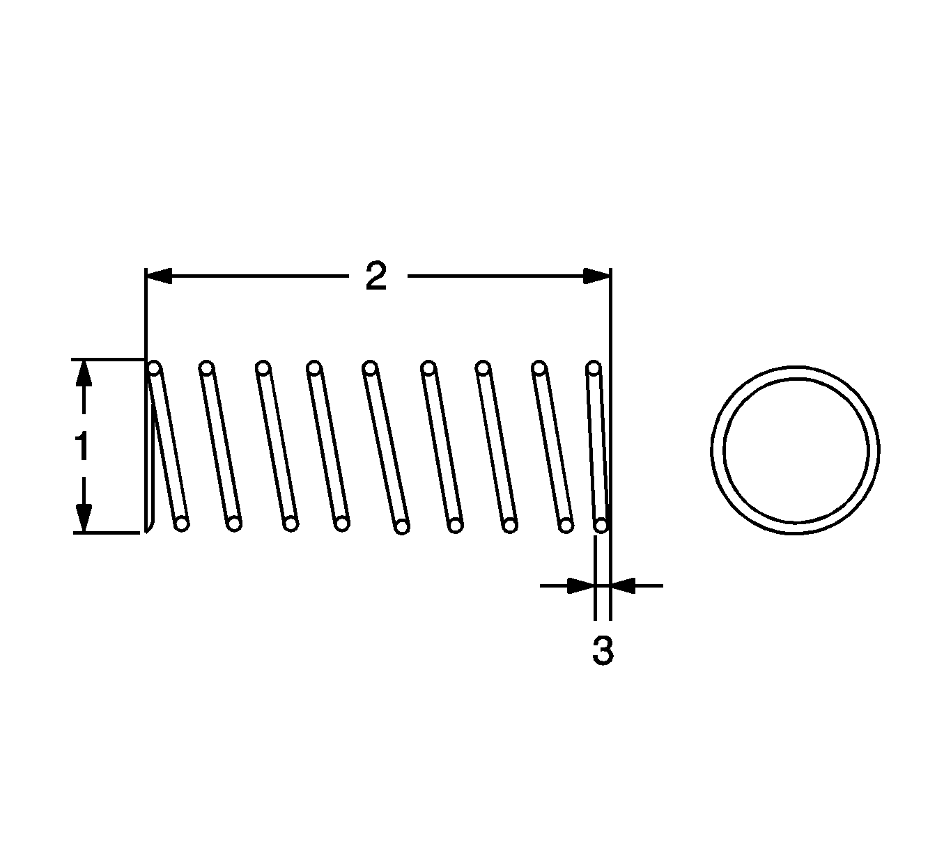
- Take the following spring measurements, outer diameter (1), free length (2), and wire diameter (3).
- If the measured value is too low or too high, replace the spring.
- Refer to the Intermediate Control Valve Body Springs Specifications table in Transmission General Specifications .

