Caution: Do not use these illustrations to troubleshoot without consulting the diagnostic trouble code (DTC) charts. The DTC charts give additional safety precautions and detailed instructions for each test. Failure to follow proper precautions can result in injury from unintended air bag deployment.
Diagnostic Illustration 1
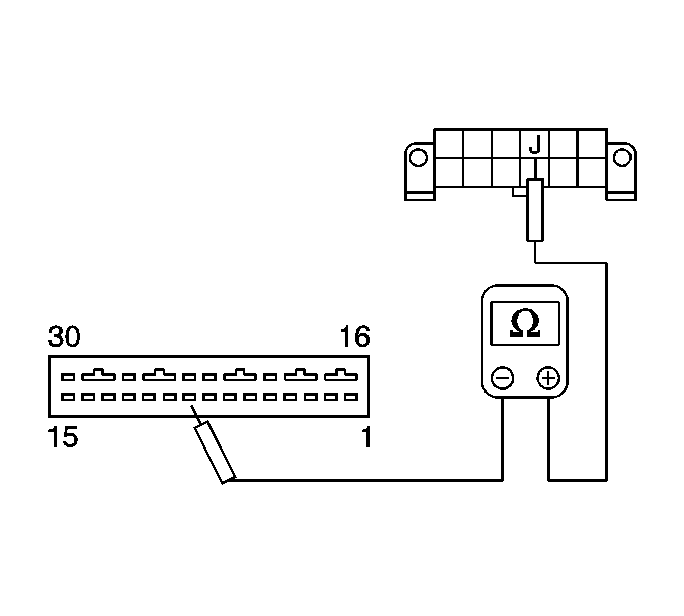
Checking the continuity between the terminal 9 of the sensing and diagnostic module and the terminal J (13) of the assembly line diagnostic link.
Diagnostic Illustration 2
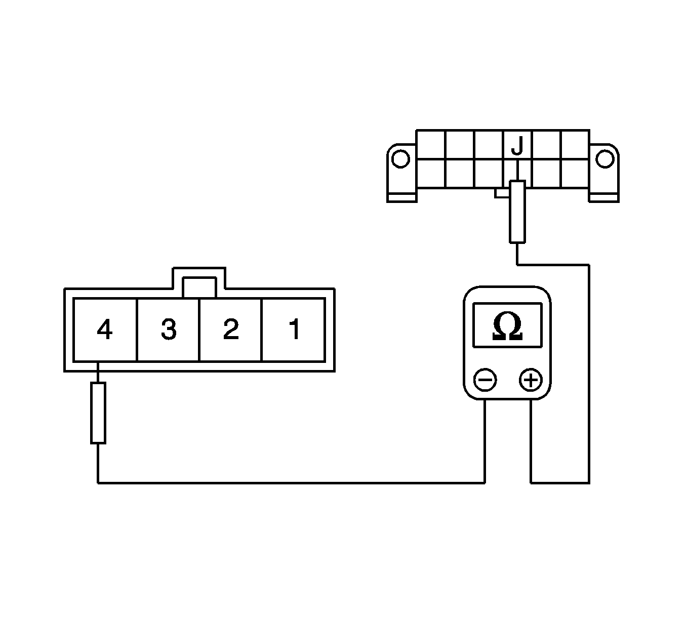
Checking the continuity on the instrument harness side between the terminal J (13) of the assembly line diagnostic link and the terminal 4 of the connector C208.
Diagnostic Illustration 3
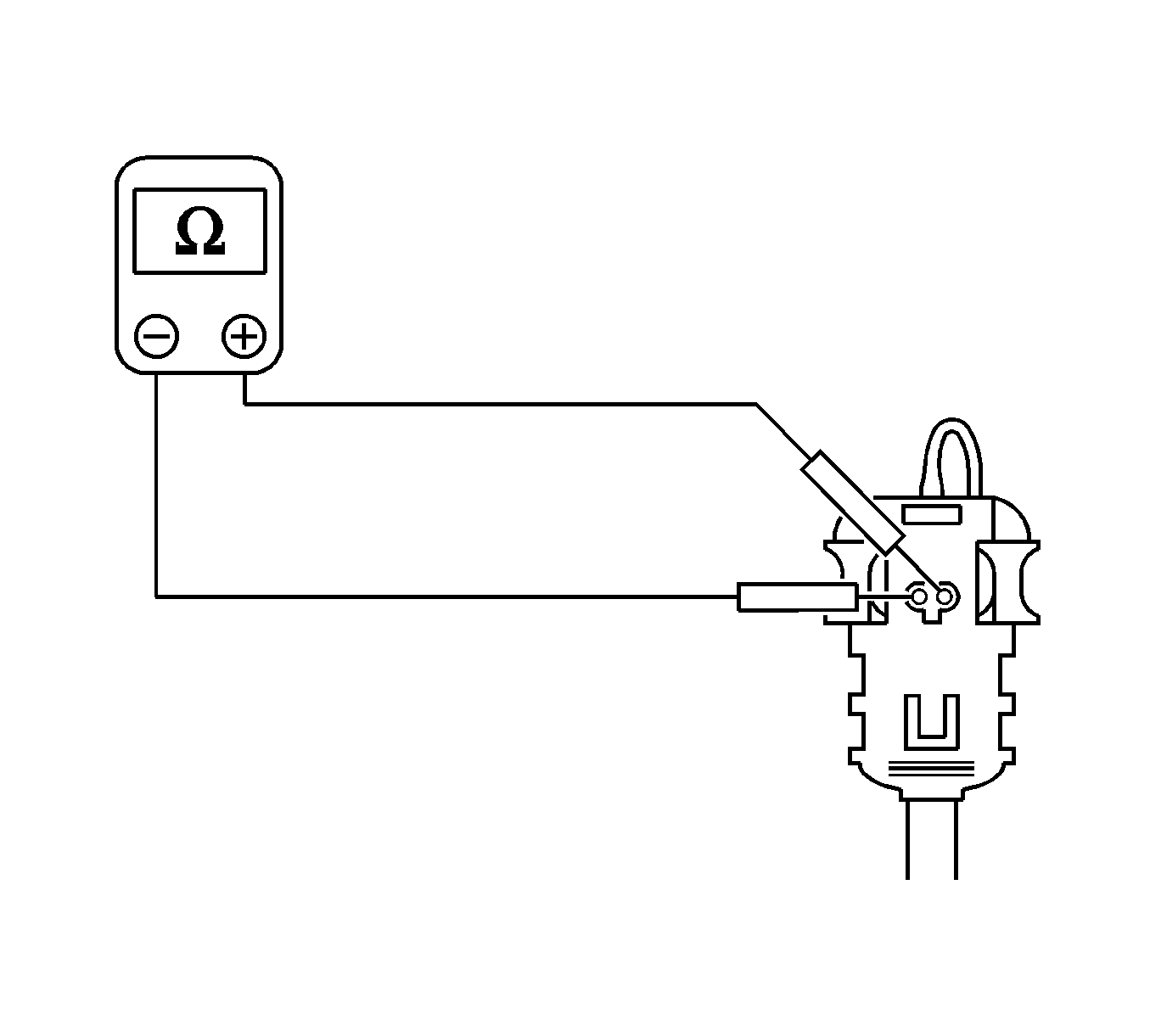
Measuring the wiring harness for the continuity of the driver side air bag module circuit.
Diagnostic Illustration 4
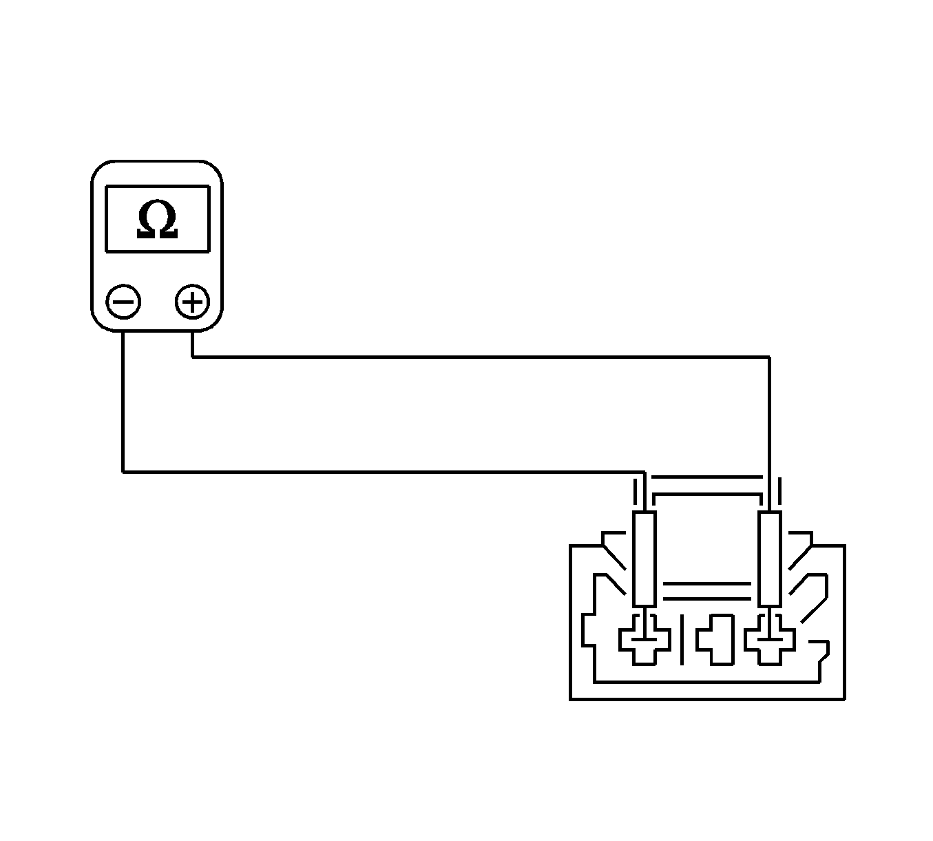
Checking the continuity of the driver air bag circuit on the sensing and diagnostic module (SDM) side of the coil spring connector.
Diagnostic Illustration 5
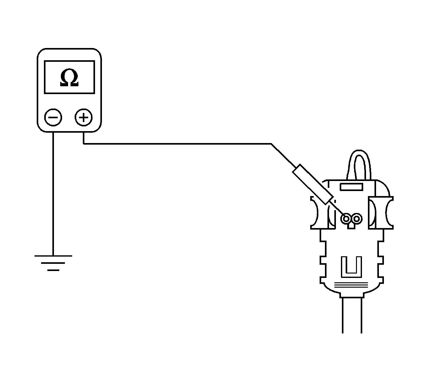
Checking the driver air bag circuit for a short to ground with the sensing and diagnostic module disconnected.
Diagnostic Illustration 6
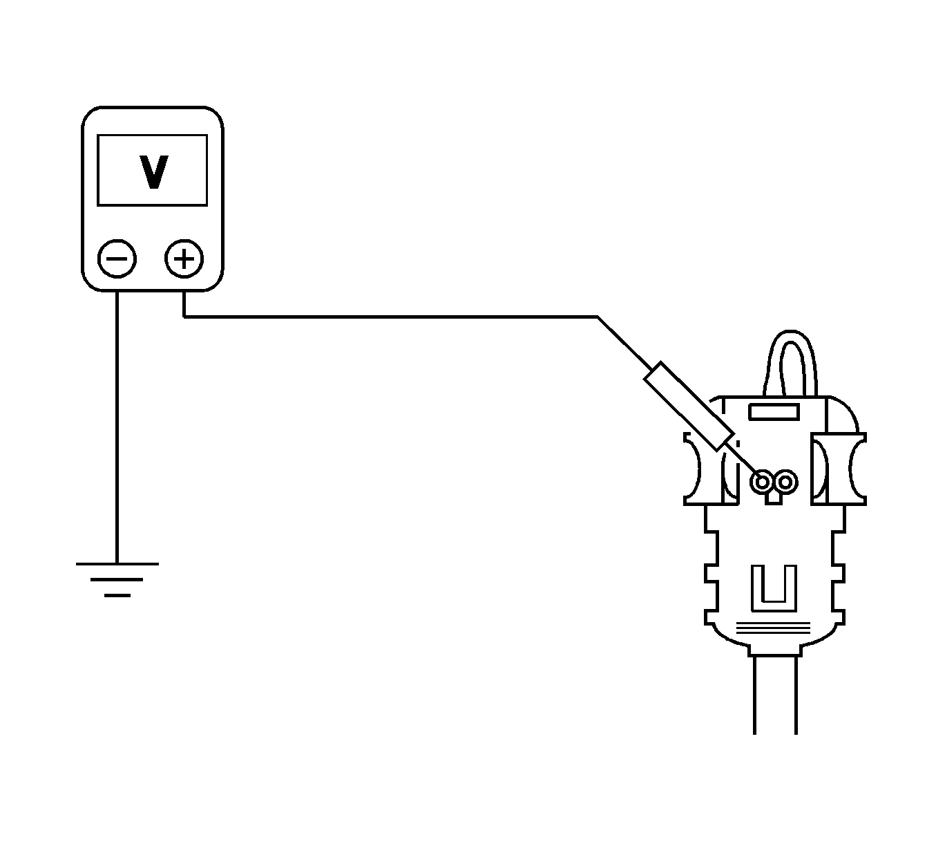
Checking the driver air bag circuit for a short to voltage.
Diagnostic Illustration 7
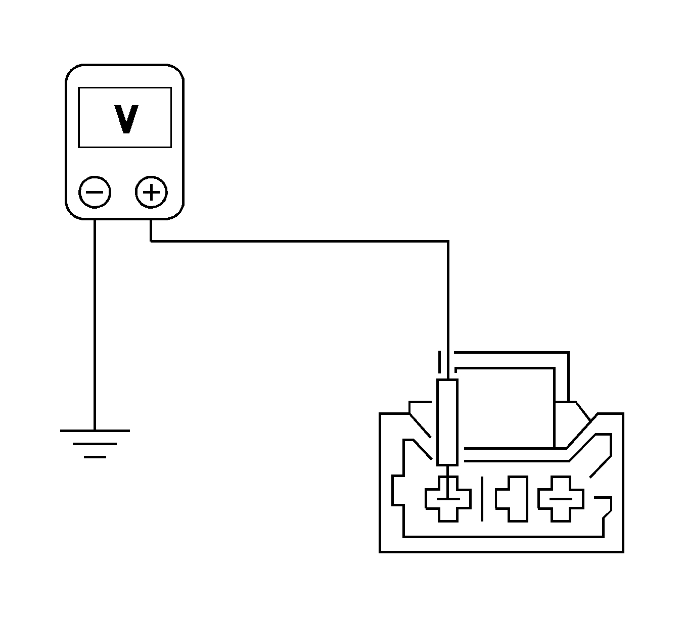
Checking the coil spring connector for a short to voltage on the sensing and diagnostic module side.
Diagnostic Illustration 8
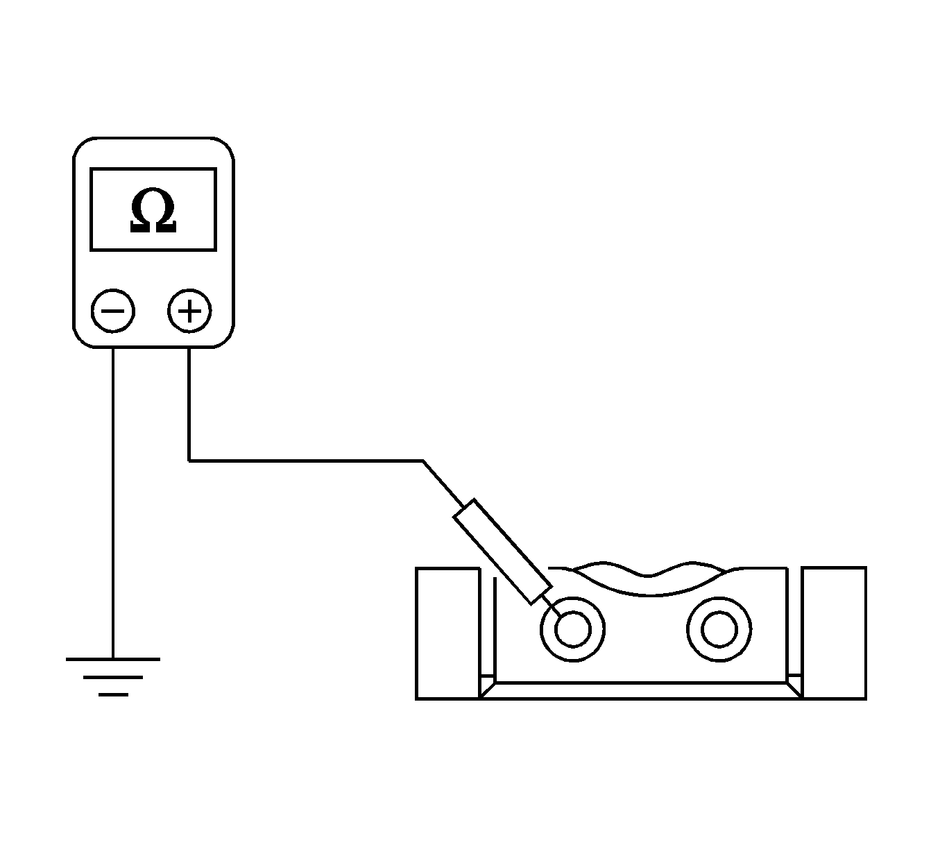
Checking the passenger air bag circuit continuity on the sensing and diagnostic module side of the connector.
Diagnostic Illustration 9
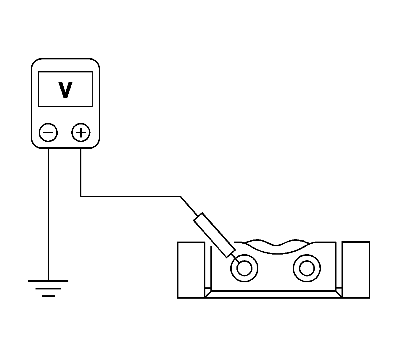
Checking the passenger air bag circuit for a short to ground.
Diagnostic Illustration 10

Checking the passenger air bag circuit for a short to voltage.
Diagnostic Illustration 11
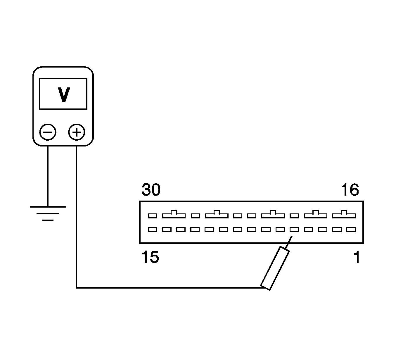
Checking the sensing and diagnostic module voltage supply at the terminal 5.
Diagnostic Illustration 12
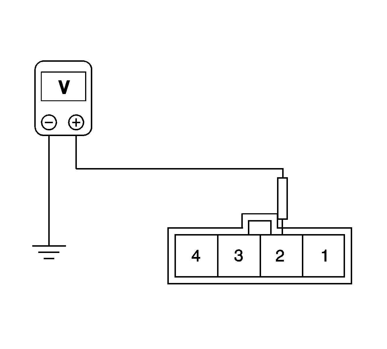
Checking the voltage supply on the instrument harness side at the terminal 2 of the connector C208.
Diagnostic Illustration 13
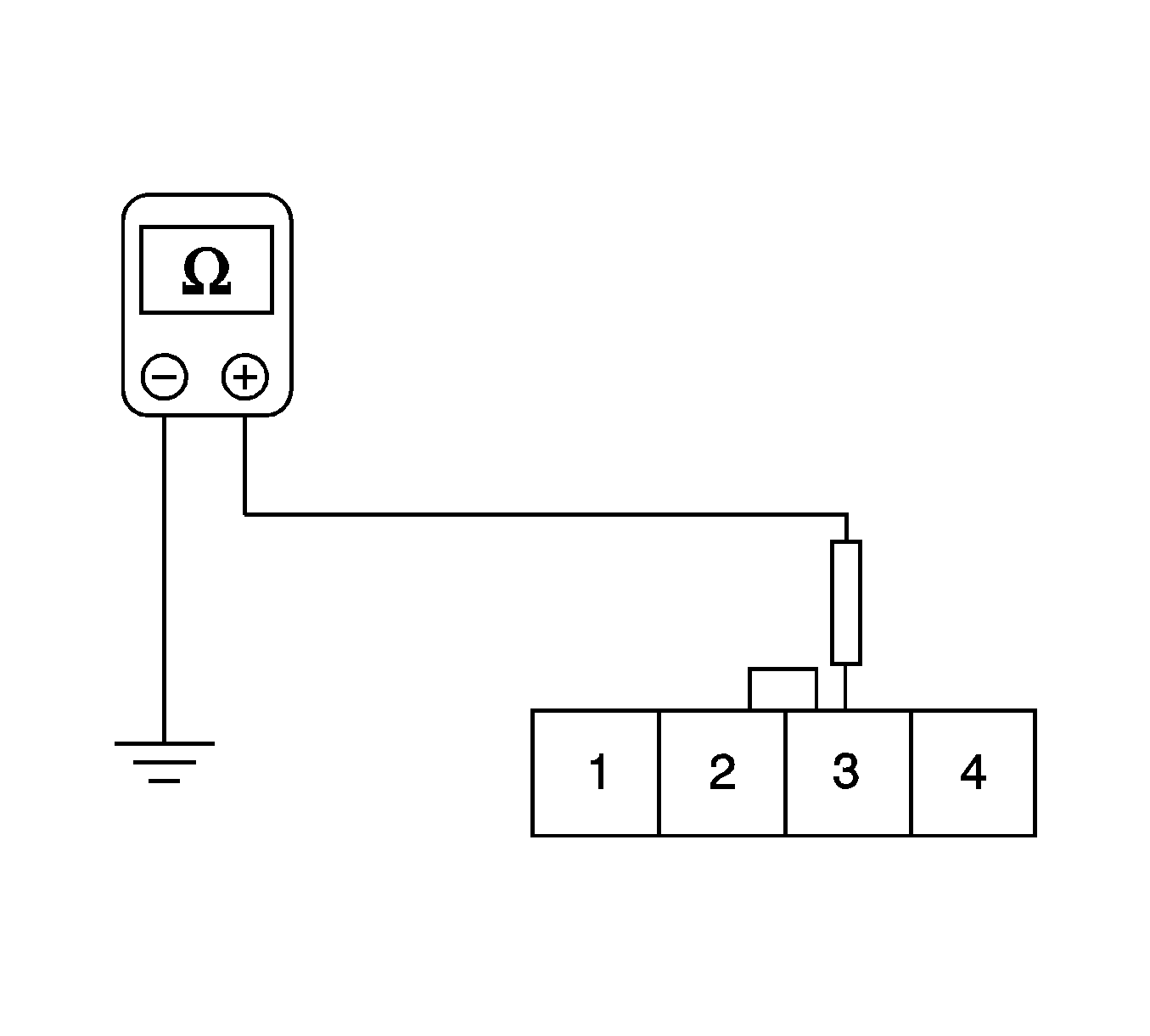
Checking for a short to ground on the sensing and diagnostic module side of the supplemental inflatable restraints harness at the terminal 3 of the connector C208.
Diagnostic Illustration 14
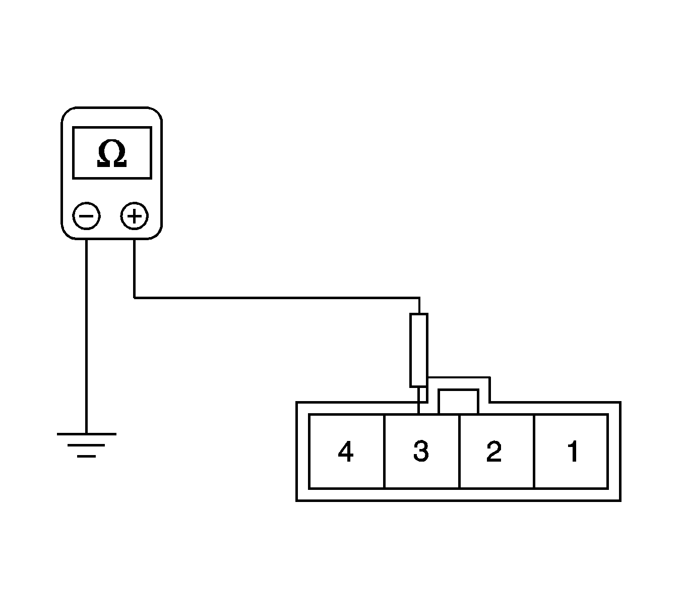
Checking for a short to ground in the instrument harness on the instrument harness side at the terminal 3 of the connector C208.
Diagnostic Illustration 15
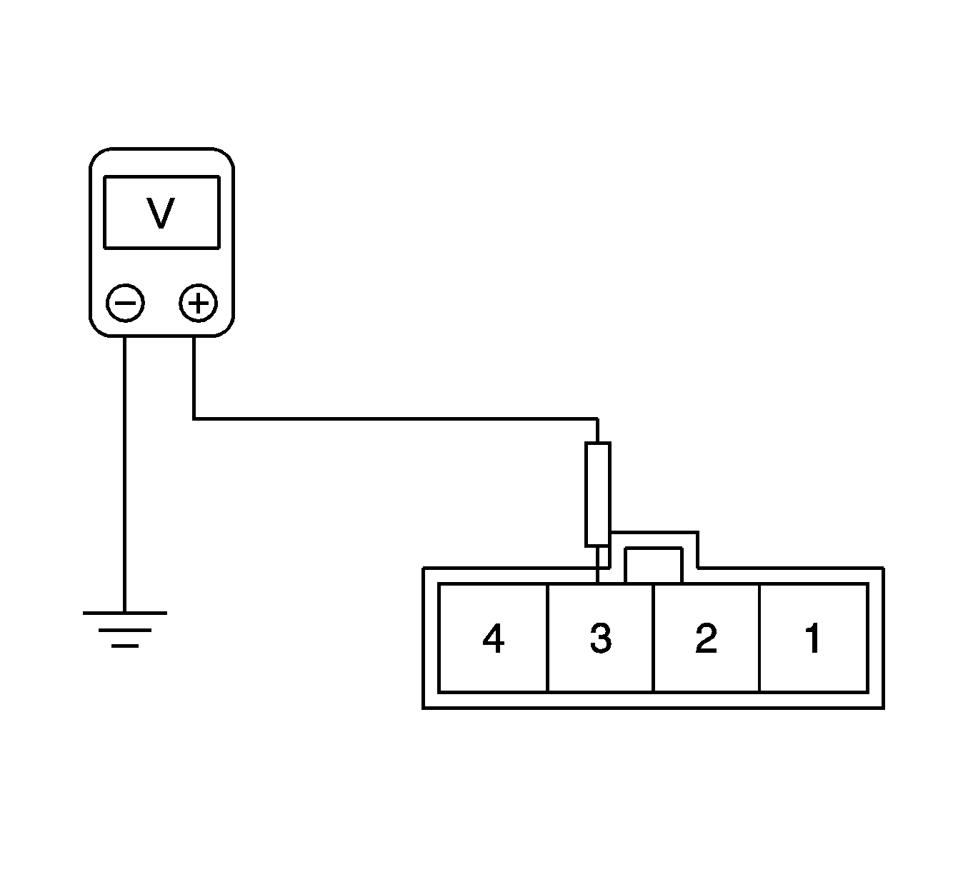
Checking the voltage of the warning lamp circuit on the instrument harness side at the terminal 3 of the connector C208.
Diagnostic Illustration 16

Checking the driver seat belt pretensioner circuit continuity on the sensing and diagnostic module side of the connector.
Diagnostic Illustration 17

Checking the driver seat belt pretensioner circuit for a short to ground.
Diagnostic Illustration 18

Checking the driver seat belt pretensioner circuit for a short to voltage.
Diagnostic Illustration 19

Checking the passenger seat belt pretensioner circuit continuity on the sensing and diagnostic module side of the connector.
Diagnostic Illustration 20

Checking the passenger seat belt pretensioner circuit for a short to ground.
Diagnostic Illustration 21

Checking the passenger seat belt pretensioner circuit for a short to voltage.
