Tools Required
J 39580 (DW 010-010) Power Pack Engine and Transaxle Assembly Support Remover/Installer
Removal Procedure
- Discharge the air conditioning (A/C) system, if equipped.
- Drain the power steering oil, if equipped.
- Relieve the fuel system pressure. Refer to Fuel Pressure Relief for the 1.0L engine.
- Disconnect the negative battery cable.
- Remove the air filter, resonator with snorkel assembly (a). Refer to Air Cleaner Assembly Replacement for the 1.0L engine.
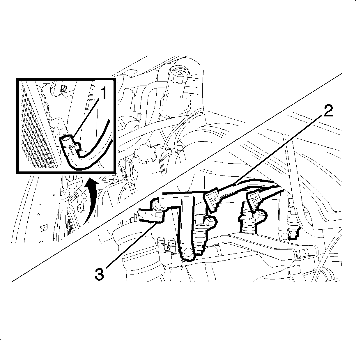
- Disconnect the radiator lower hose and drain the coolant (1). Refer to Cooling System Draining and Filling .
- Disconnect the fuel line inlet hose and the fuel injector wire connectors from the fuel rail (2, 3).
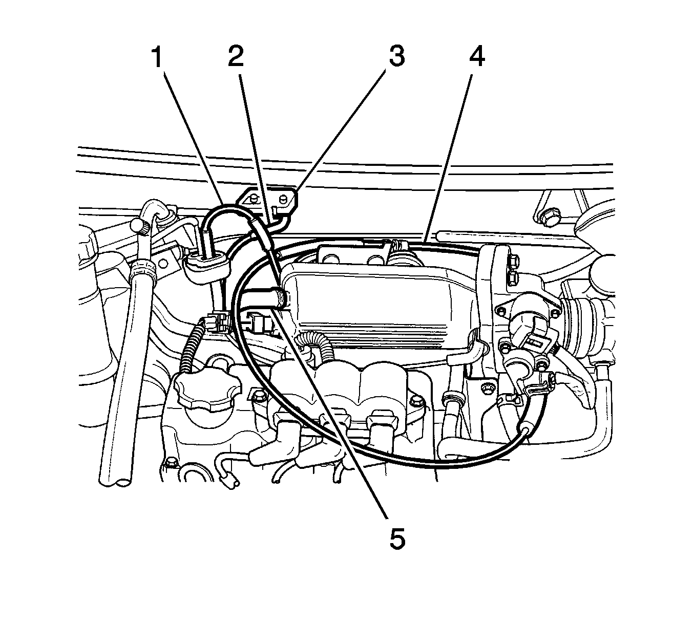
- Disconnect the throttle cable (4).
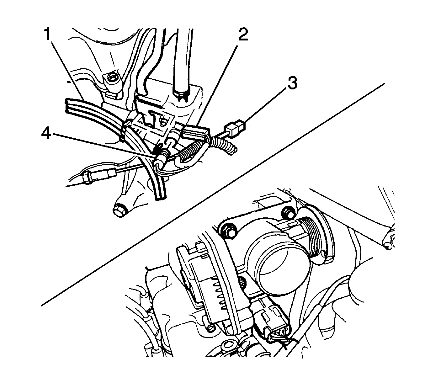
- Disconnect manifold absolute pressure (MAP) sensor connector (3).
- Disconnect the canister solenoid connector (1).
- Disconnect the brake booster vacuum hose (5).
- Disconnect the evaporative emission (EVAP) canister vacuum hose.
- Disconnect intake air temperature (IAT) sensor connector.
- Disconnect the engine coolant temperature (ECT) sensor connector (4).
- Disconnect the coolant temperature sensor connector (2).
- Disconnect the oxygen sensor connector (3).
- Disconnect camshaft position (CMP) sensor connector and crankshaft position (CKP) sensor connector.
- Disconnect the heat core inlet hose.
- Disconnect the throttle body coolant outlet hose.
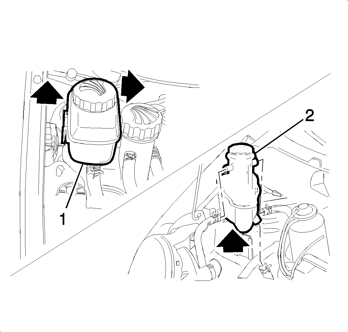
- Remove the power steering oil tank (2), if equipped. Refer to Power Steering Fluid Reservoir Replacement .
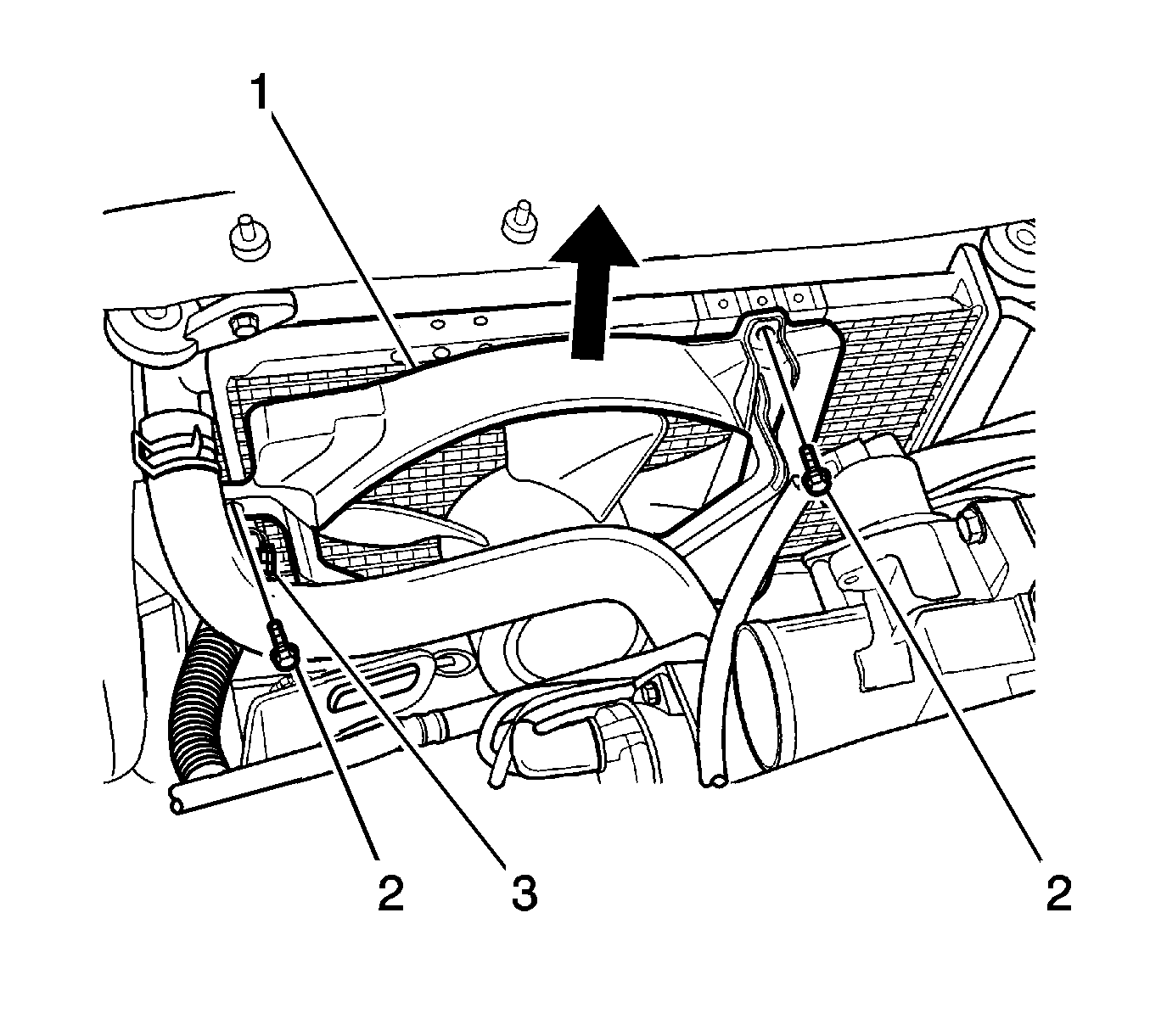
- Remove the coolant surge tank (2).
- Disconnect the electrical connector (3).
- Loosen the bolts (2).
- Take out the coolant fan assembly as shown in the picture (1).
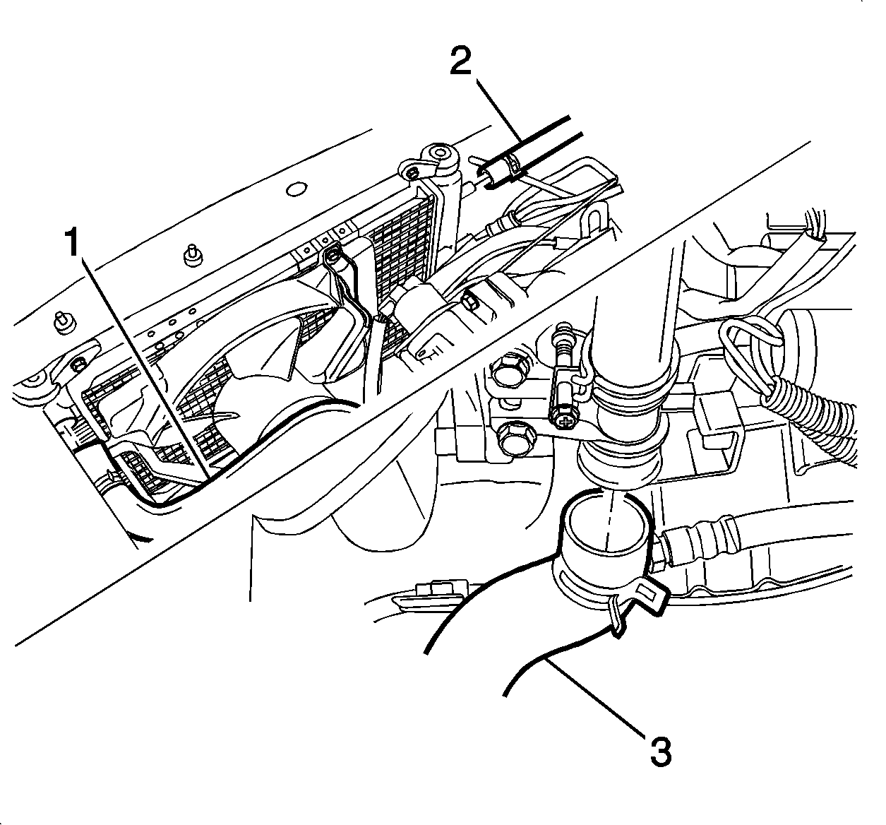
- Disconnect and remove the radiator upper hose (1).
- Disconnect and remove the radiator surge tank hose (2).
- Disconnect and remove the radiator lower hose (3).
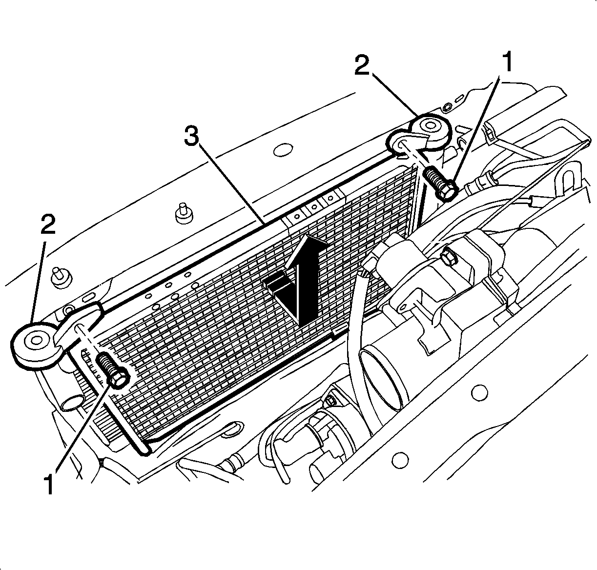
- Loosen the bolts (2).
- Remove the radiator mounting brackets (1).
- Take out the radiator as shown in the picture (3).
- Disconnect the connectors, the pipes, and the hoses, if equipped, with the A/C system and power steering.
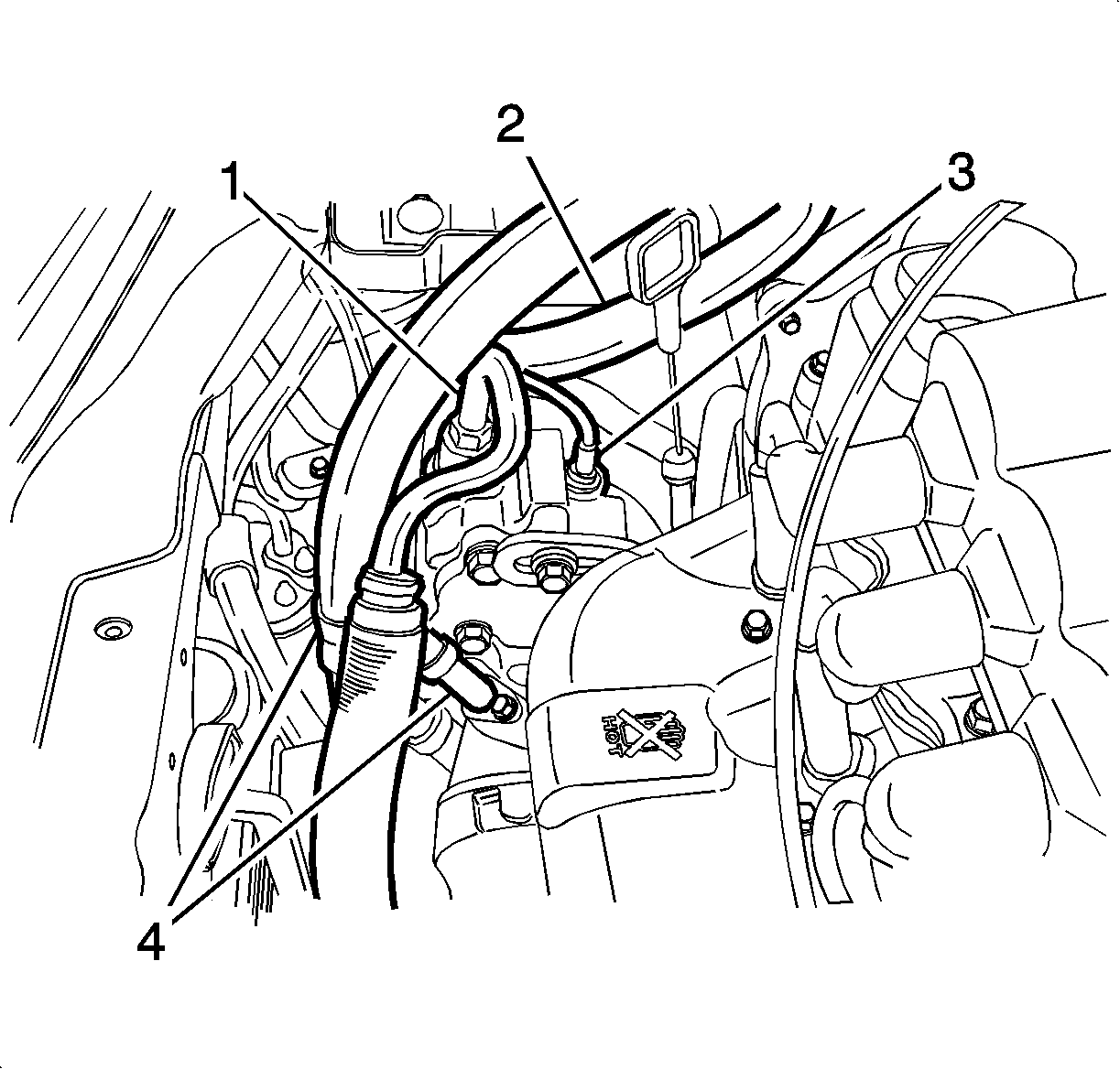
- Disconnect the power steering pump (2).
- Disconnect the hose from the power steering pump (1).
- Disconnect the pipe from the power steering pump (1).
- Disconnect the air conditioning low and high pressure pipes (4).
- Disconnect the power steering hose.
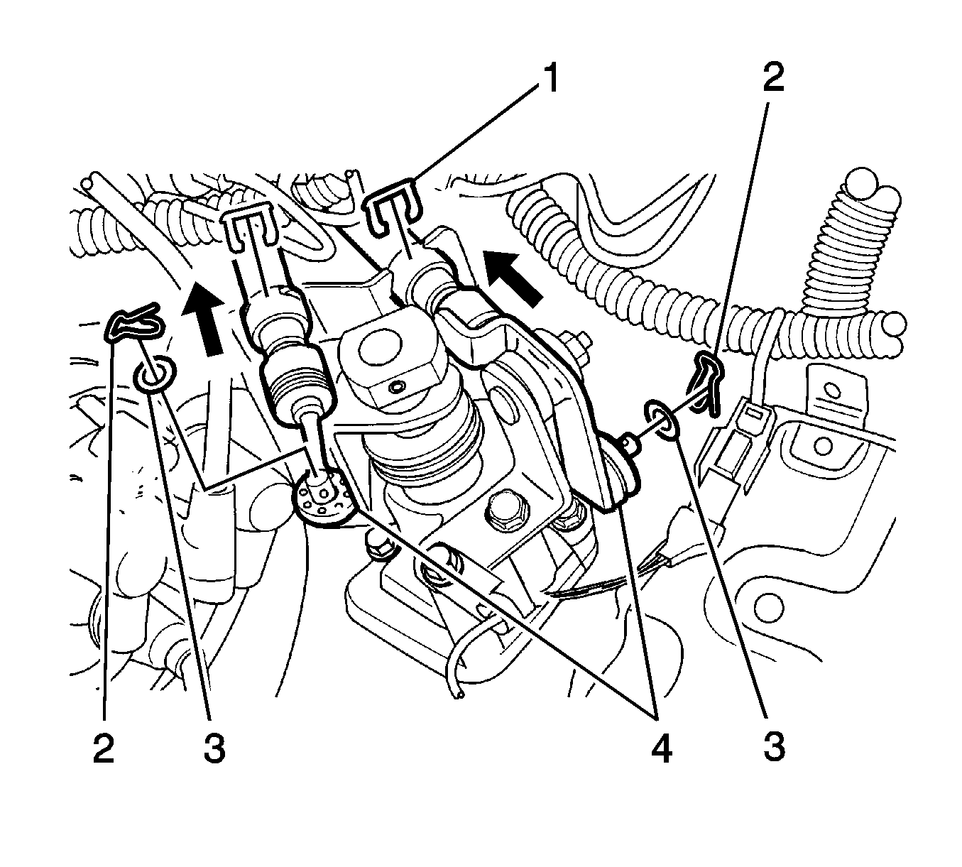
- Remove the select and shift cable pin (2).
- Remove the select and shift cable washer (3).
- Disconnect the select and shift cable (4).
- Remove the E-ring (1).
- Remove the engine electrical wire bending strap.
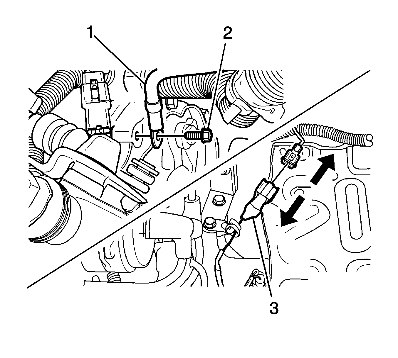
- Loosen the transaxle case ground connection line bolt (2).
- Disconnect the transaxle case ground connection line (1).
- Disconnect the backup lamp switch electrical connector (3).
- Disconnect the gear position sensor electrical connector.
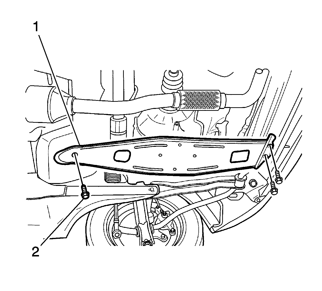
- Remove the transaxle under cover (1) and bolts (2).
- Remove the oil drain plug to drain transaxle oil.
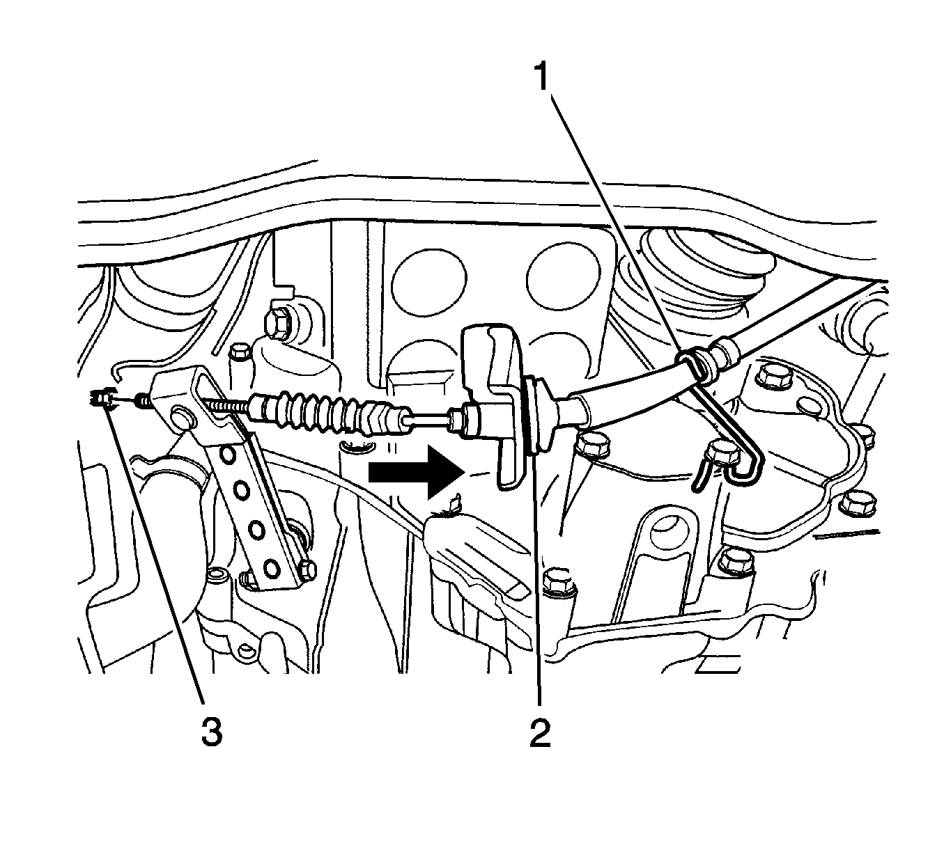
- Loosen the cable adjusting nuts (3).
- Disconnect the cable from the wire clip (1).
- Disconnect the cable from the transaxle mount hole (2).
- Loosen the speedometer cable nut (1).
- Disconnect the speedometer cable (2).
- Disconnect the vehicle speed sensor electrical connector, if equipped.
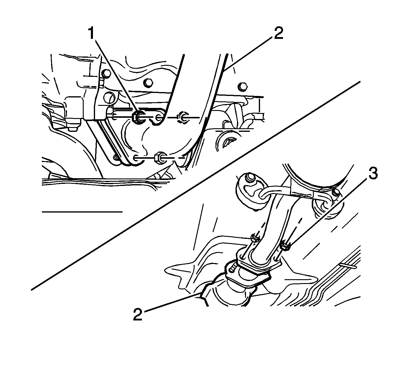
- Loosen the exhaust pipe nuts (1).
- Remove the gasket and disconnect the pipe (4).
- Loosen the front exhaust pipe nuts (3).
- Remove the front exhaust pipe (2).
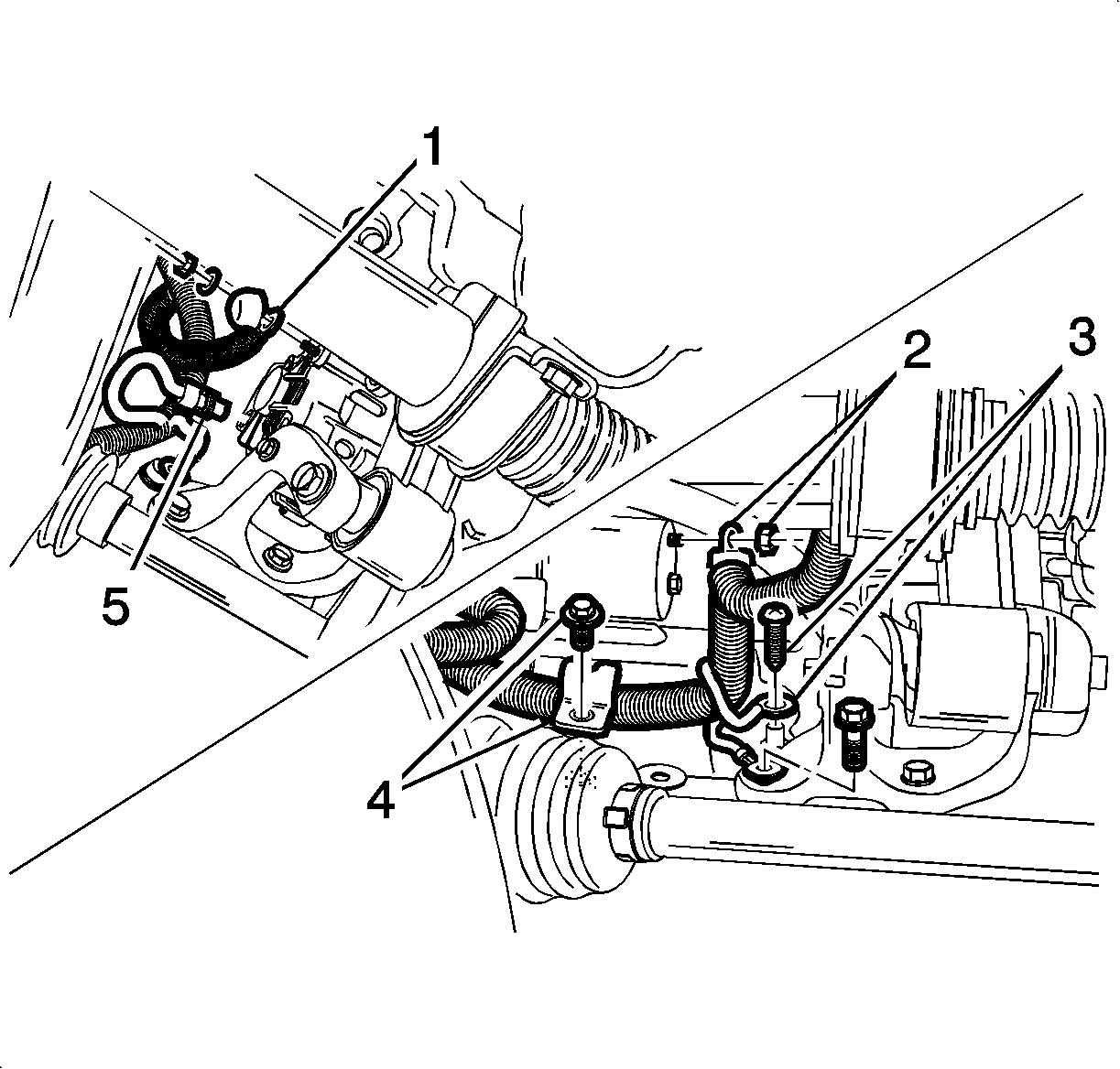
- Disconnect the oil pressure switch electrical connector (3).
- Disconnect the generator B+ terminal (1).
- Disconnect the generator electrical connector (5).
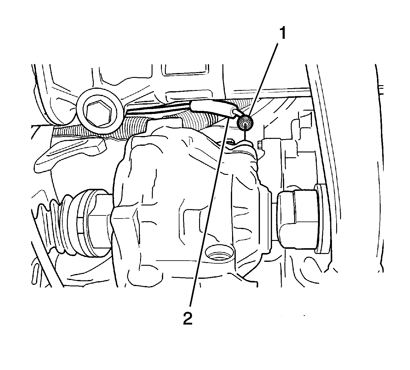
- Disconnect the starter electrical connector (2).
- Disconnect the electrical wire strap (4).
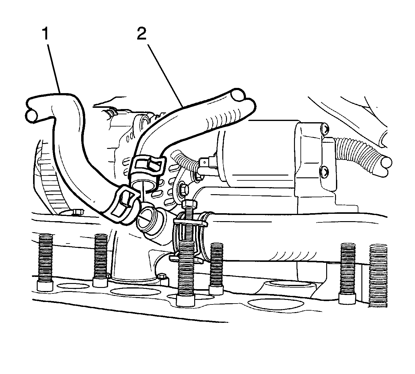
- Disconnect the surge tank coolant return hose (1) and the heater outlet hose (2).
- Remove both of the front tires. Refer to Tire and Wheel Removal and Installation .
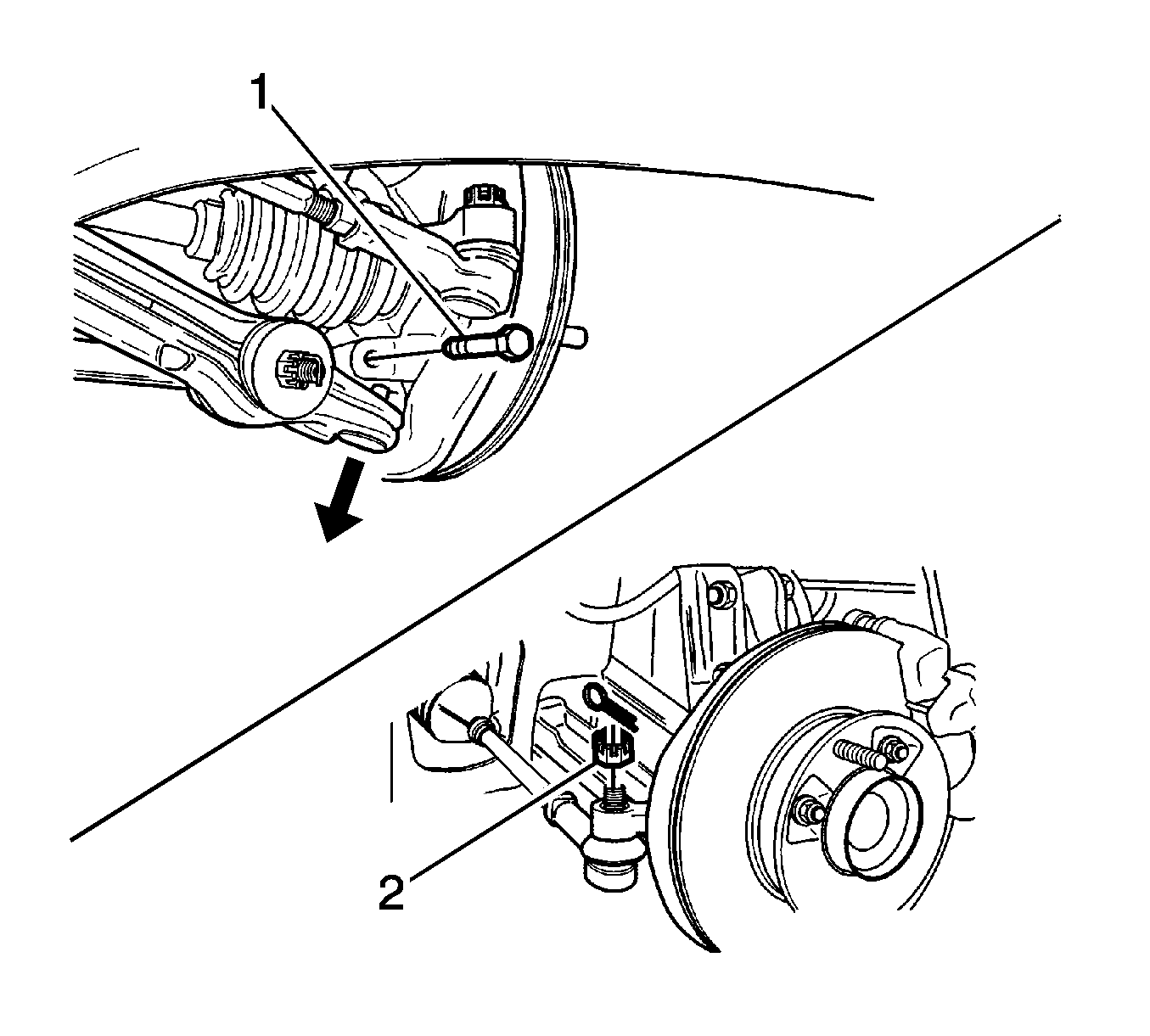
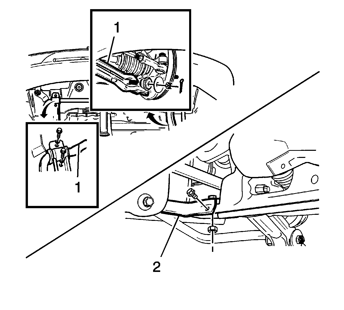
- Remove the control arm stud bolt (1).
- Tie rod end castellated nut (2).
- Remove both of the front wheels. Refer to Control Arm Replacement .
- Remove the left/right front longitudinal member (2) and stabilizer bar (1). Refer to Stabilizer Shaft Replacement .
- Loosen the caulking nut.
- Remove the drive axle on the wheel side (1).
- Insert a driver between the transaxle case and the drive axle joint case (2).
- Remove the drive axle on the differential side as shown (3). Refer to Diagnostic Starting Point - Front Drive Axle .
- Remove the damping bush assembly bolt and nut (1).
- Remove the engine mount front bracket and the damping bush assembly (2, 3).
- Remove the right and left crossmember (1, 2). Refer to Front Suspension Crossmember Replacement .
- Remove the left crossmember (2).
- Loosen the engine mount intermediate bracket nut (2).
- Loosen the engine mount intermediate bracket nut (1).
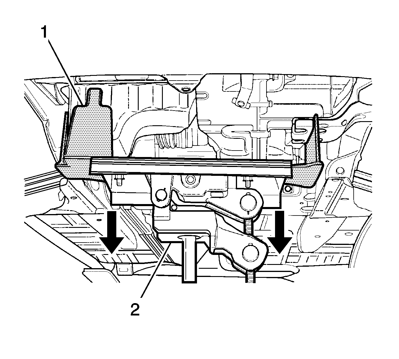
- Support the oil pan with J 39580 (1) .
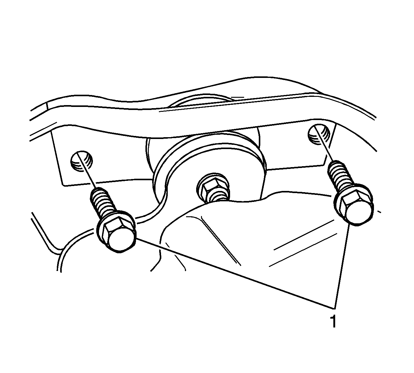
- Loosen the bolt and nut from the engine mount lower bracket (1).
- Loosen the bolt from the body bracket (2).
- Remove the engine mount reaction rod (3).
- Loosen the transaxle mount bolts (1) and remove the mount.
- Remove the engine/transaxle assembly by slowly lowering the special tool (1).
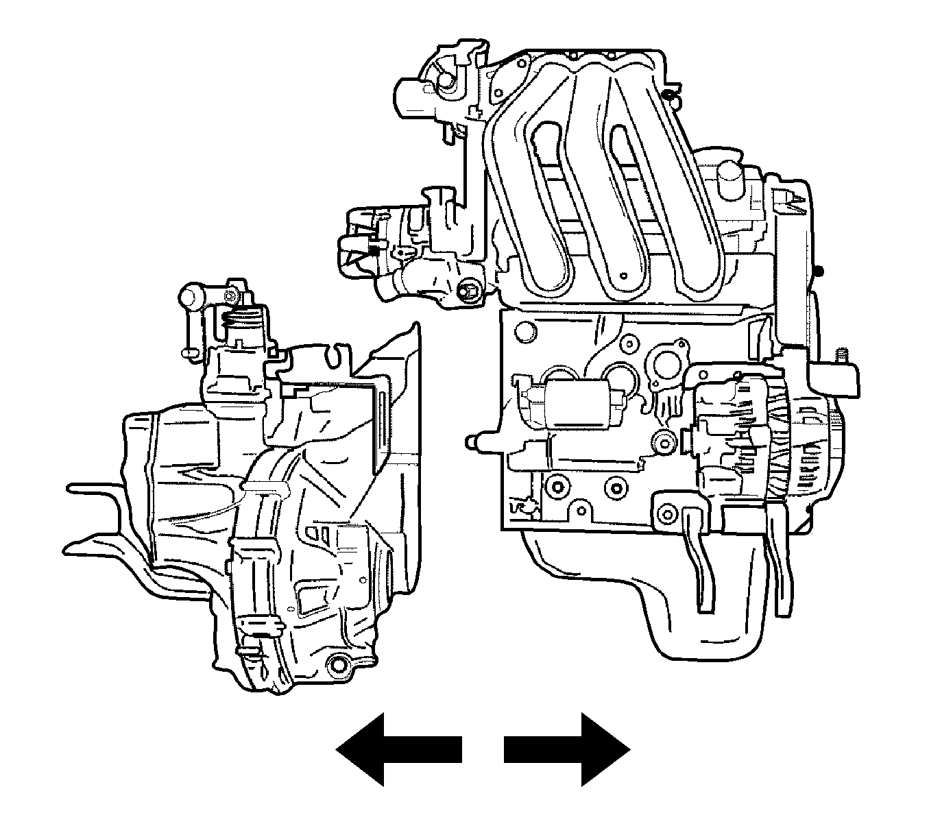
- Remove the transaxle from the engine/transaxle assembly. Refer to Transmission Replacement for the Y4M transmission.
- Remove some parts to be equipped with the engine assembly. Refer to Crankshaft Replacement .
Caution: Avoid breathing the A/C Refrigerant 134a (R-134a) and the lubricant vapor or the mist. Exposure may irritate the eyes, nose, and throat. Work in a well ventilated area. In order to remove R-134a from the A/C system, use service equipment that is certified to meet the requirements of SAE J 2210 (R-134a recycling equipment). If an accidental system discharge occurs, ventilate the work area before continuing service. Additional health and safety information may be obtained from the refrigerant and lubricant manufacturers.
Caution: Refer to Battery Disconnect Caution in the Preface section.
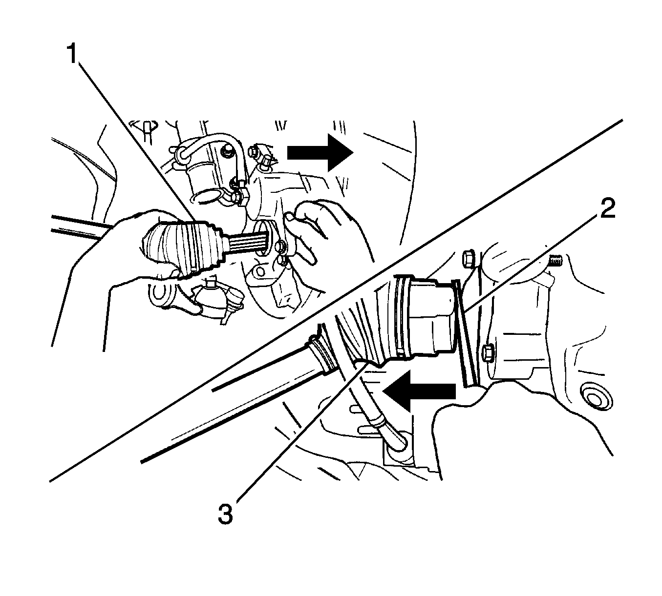
Notice: When removing the drive axle, use extreme care not to nick or cut the drive axle oil seal.
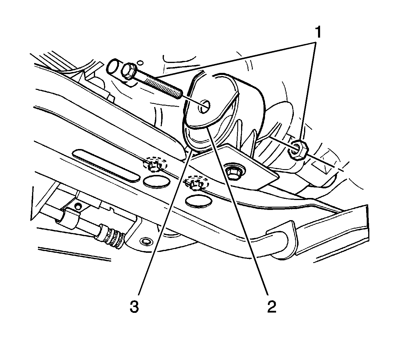
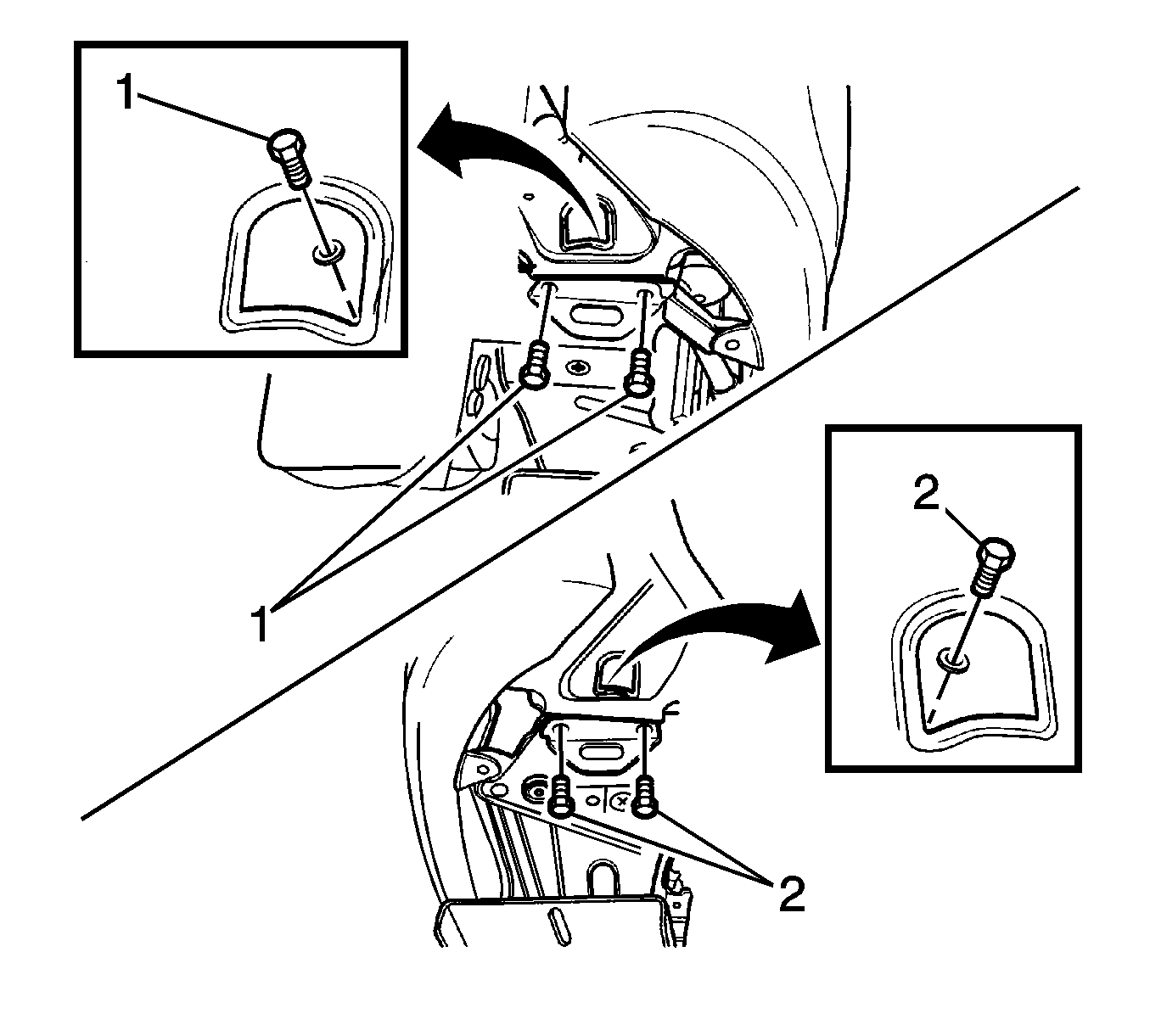
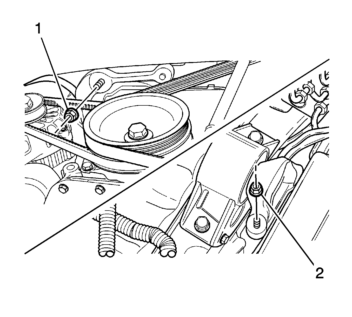
Important: Before loosening the engine mount intermediate bracket nut, the oil pan should be supported by the J 39580 .
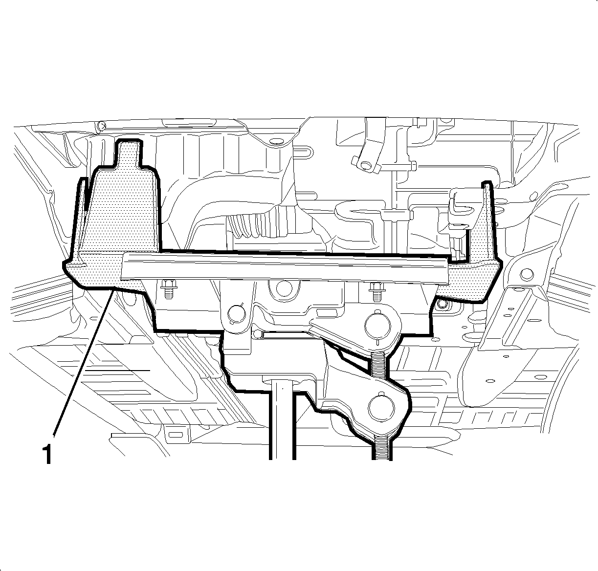
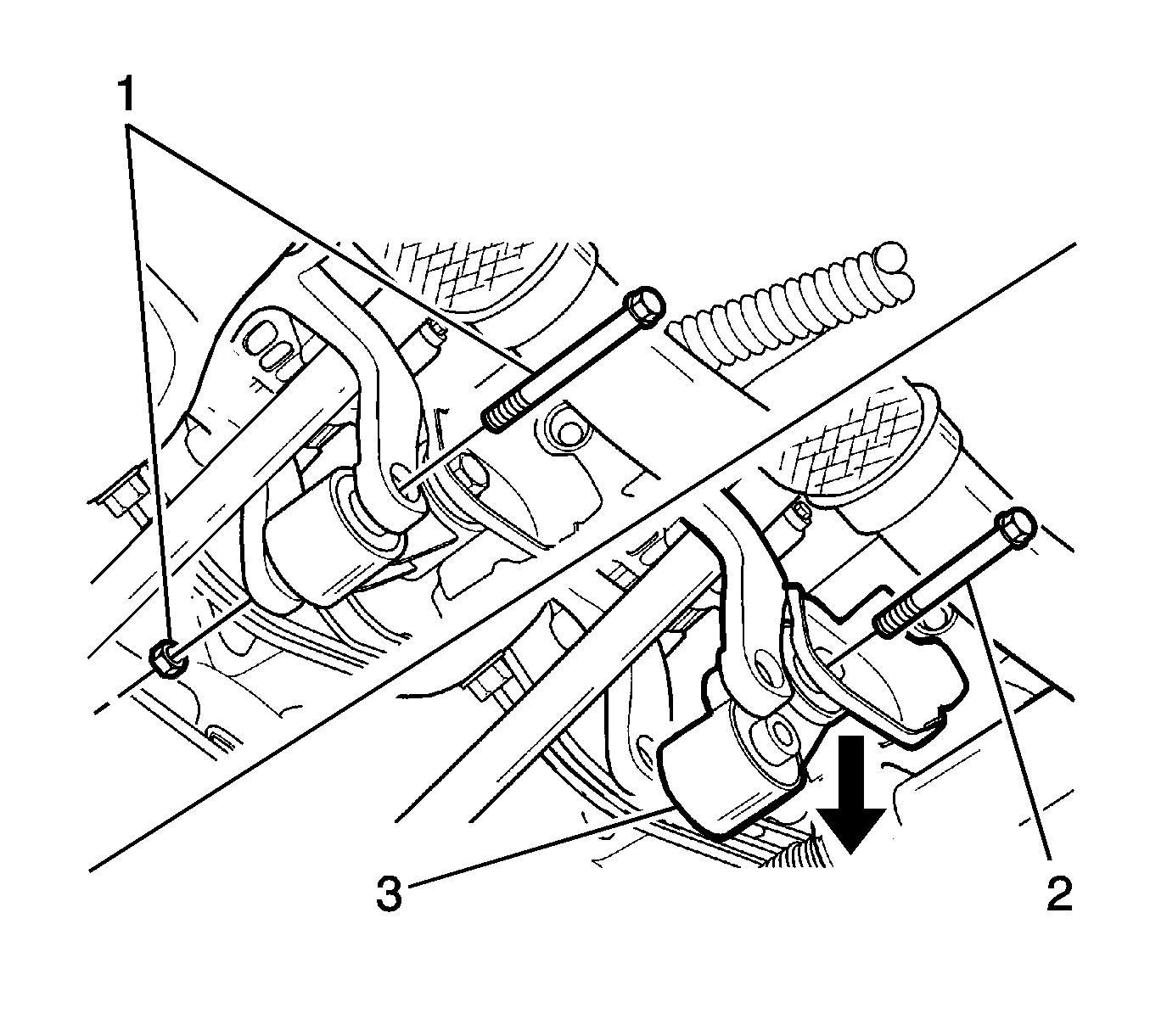
Installation Procedure
- Install parts removed from the engine assembly. Refer to Crankshaft Replacement .
- Connect the transaxle assembly to the engine assembly. Refer to Transmission Replacement for the Y4M transmission.
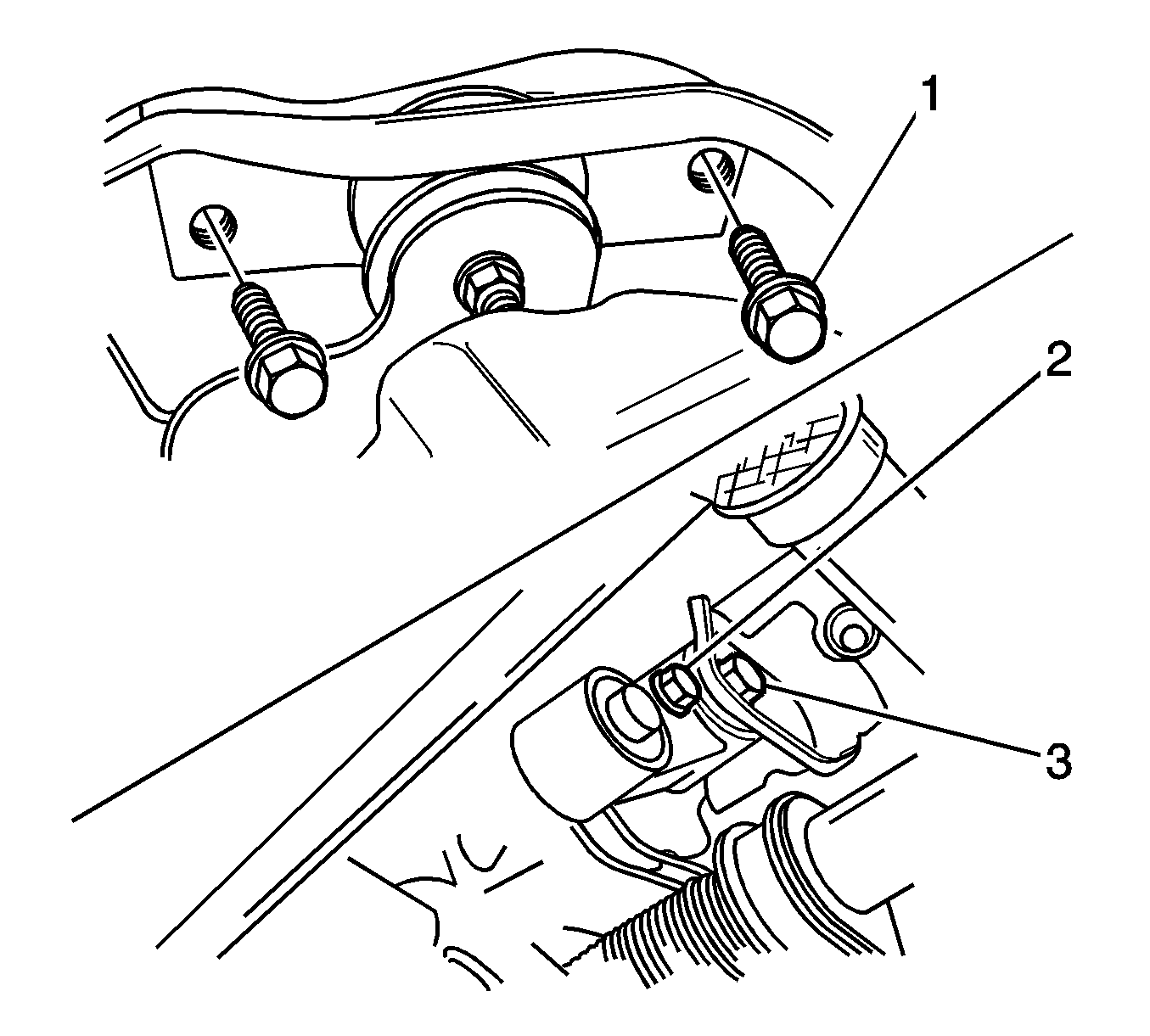
- Install the transaxle mount bolts (1).
- Install the engine mount reaction rod bolt on the body bracket side (3).
- Install the engine mount reaction rod bolt/nut on the lower bracket side (2).
- Install the engine mount intermediate bracket (1, 2).
- Install the left and right crossmember (1, 2).
- Install the front bracket bolts (1).
- Install the front damping bush bolts on the inner crossmember side (3).
- Install the damping bush bolts on the outer crossmember side (2).
- Install the front damping bush bolt and nut on the bracket side (1).
- Install the stabilizer bar (2).
- Install the stabilizer bar mounting bolt (1).
- Install the front longitudinal member with the bolt (2) and nut (1).
- Install the control arm stud and nut (2).
- Install the tie rod end (1).
- Install the front exhaust pipe with nuts (1, 2).
- Install the transaxle under cover with bolts (1).
- Install the power steering pump pressure pipe with nut (2) and fitting (1).
- Install air conditioning low/high pressure pipe (1).
- Install the radiator (1).
- Install the cooling fan.
- Install the snorkel with bolts (1).
- Check the air conditioning low/high pressure pipe O-ring seal, select/shift cable pin/washer/E-ring, the tie end joint castellated nut cotter pin, and the stabilizer castellated nut cotter pin for loss.
- Refill transaxle oil, power steering oil, and coolant after finishing all installation procedures.
- Check if the fuel inlet hose is connected with the fuel correctly.
- Connect the negative battery cable.
- Reset the engine control module (ECM). Refer to Engine Control Module Replacement for the 1.0L engine.
- Start the engine and check the engine for the normal operation.
- Recharge the air conditioning gas and check the oil coolant level.
- Check the vacuum hose, the coolant hose, the exhaust pipe, the air conditioning/power steering pipe and hose for leakage. Check if the electrical connectors are connected correctly.
Notice: Refer to Fastener Notice in the Preface section.
Tighten
Tighten the transaxle mount bolt to 45-55 N·m (33-41 lb ft).
Tighten
Tighten the reaction rod bolt on the body bracket side to 68-83 N·m (50-61 lb ft).
Tighten
Tighten the reaction rod/bolt nut on the lower bracket side to 68-83 N·m (50-61 lb ft).
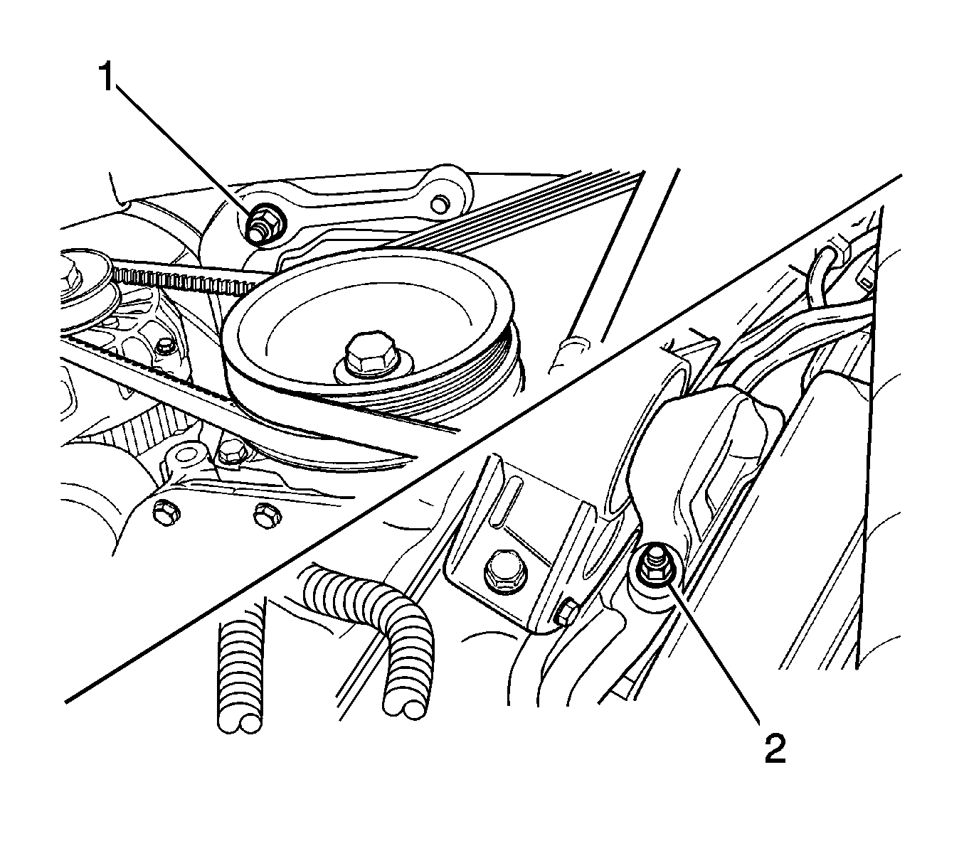
Tighten
Tighten the engine mount intermediate bracket upper/lower nut to 60-870 N·m (44-52 lb ft).
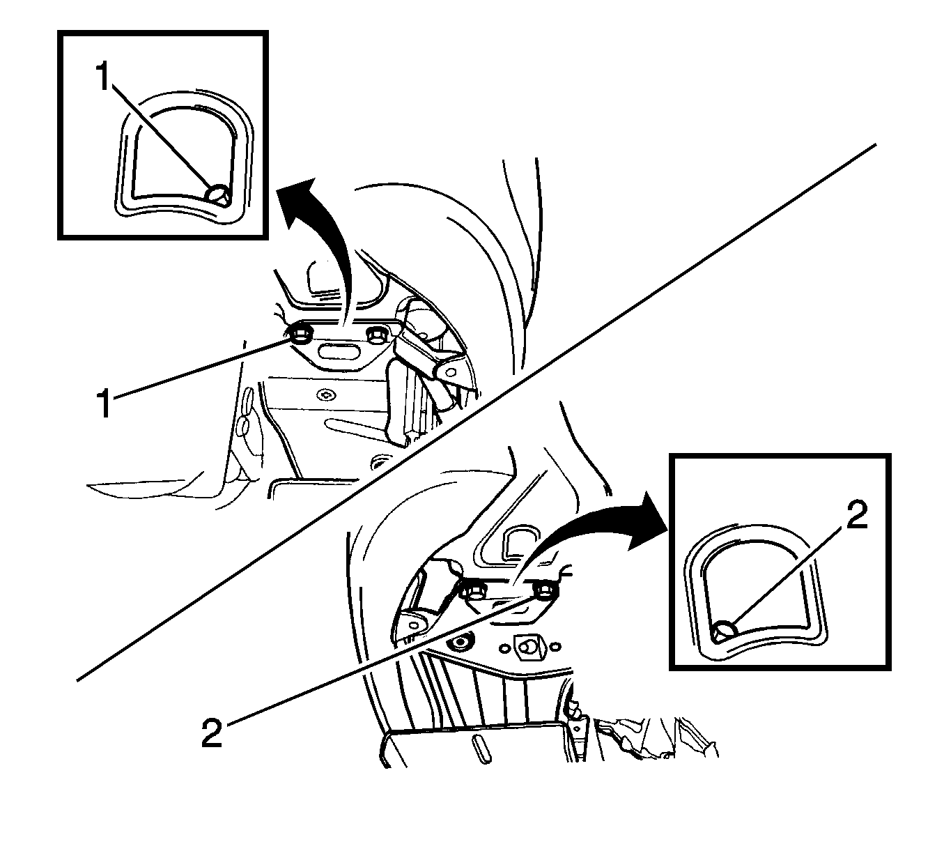
Tighten
Tighten the left/right crossmember rear side bolts to 17-27 N·m (13-20 lb ft).
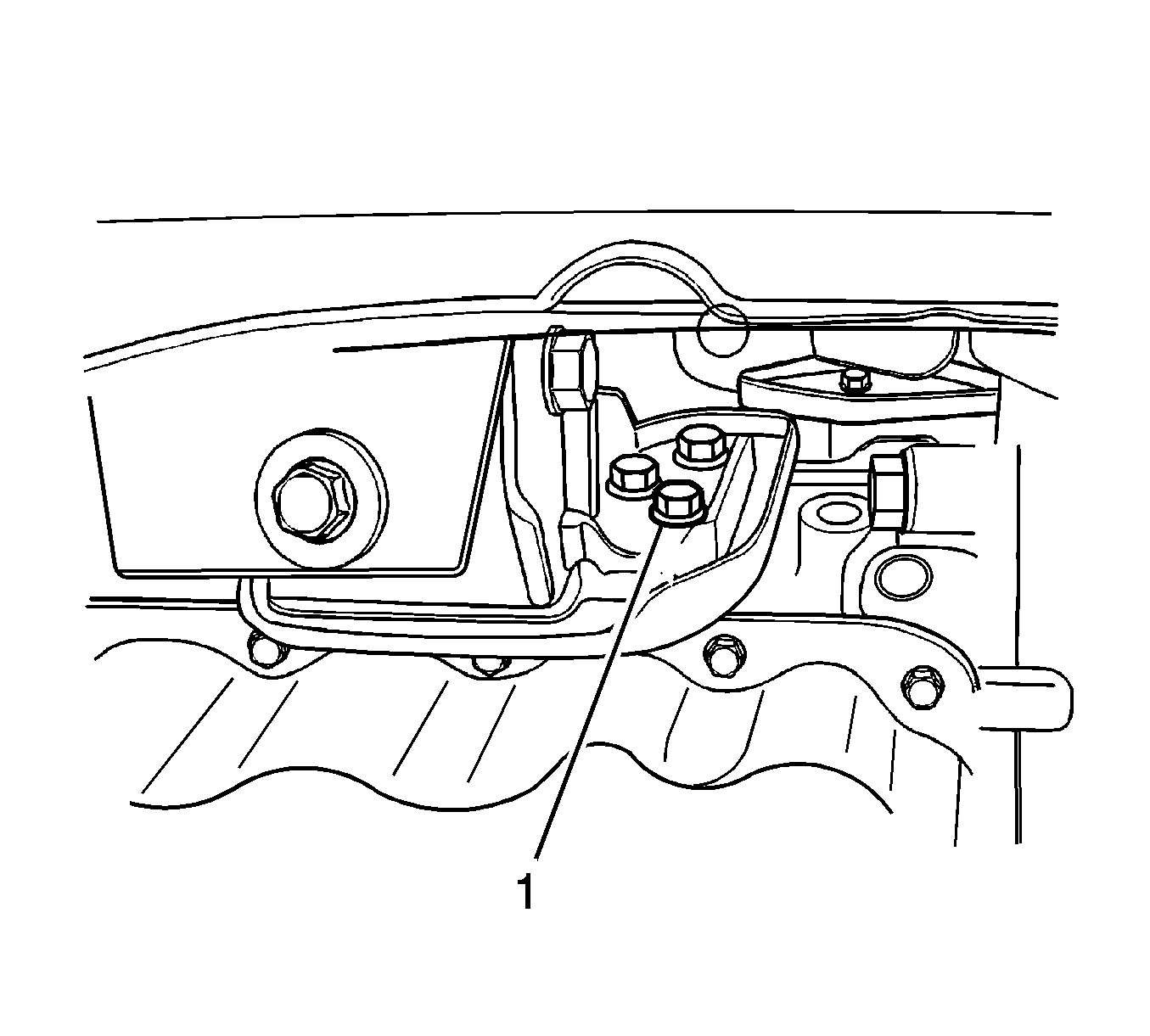
Tighten
Tighten the front bracket bolts on the cylinder block side to 35-41 N·m (25-30 lb ft).
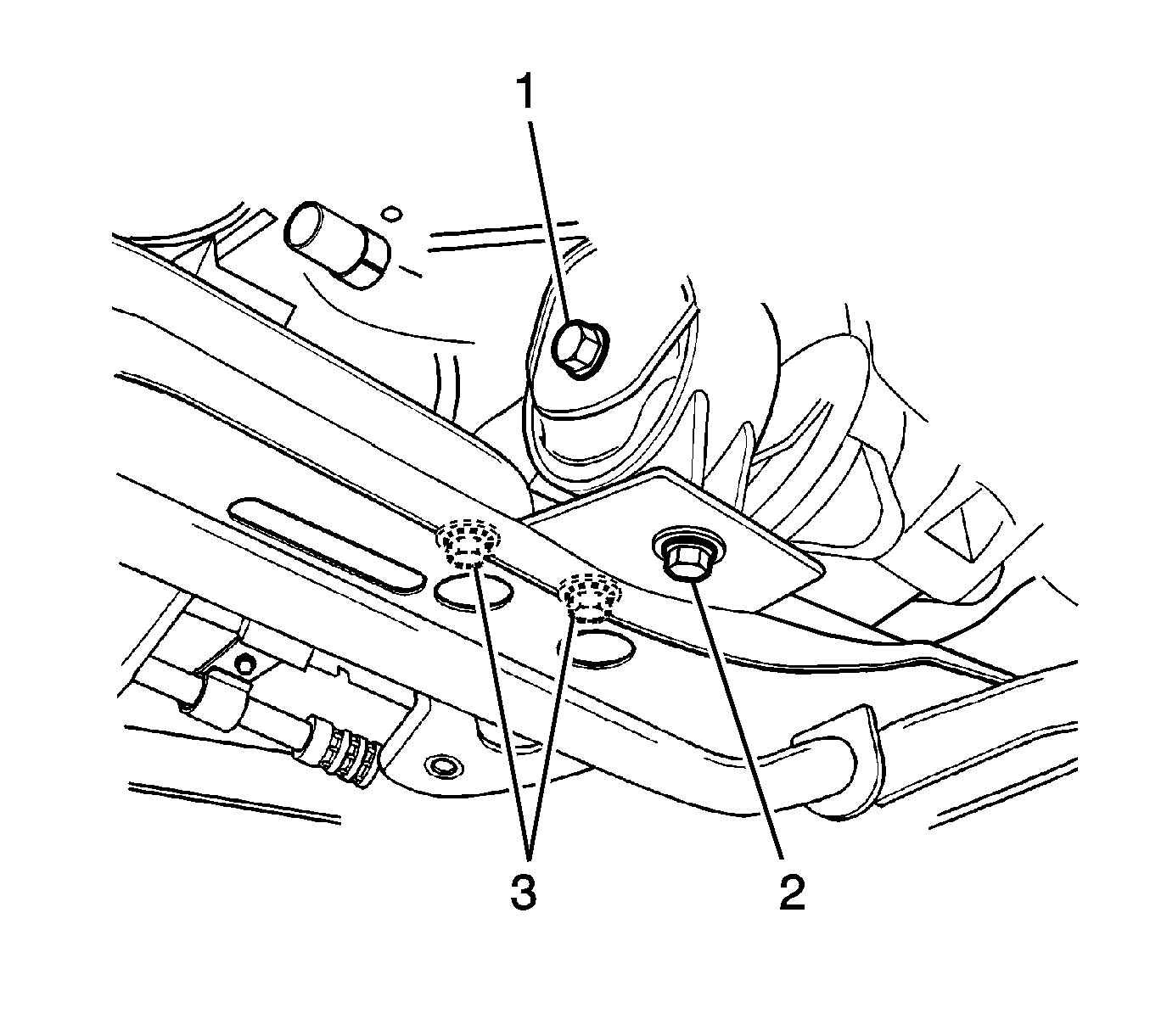
Tighten
Tighten the front damping bush bolt on the inner crossmember side to 45-55 N·m (33-41 lb ft).
Tighten
Tighten the front damping bush bolt on the outer crossmember side to 35-41 N·m (25-30 lb ft).
Tighten
Tighten the front damping bush bolt and nut on the bracket side to 68-83 N·m (50-61 lb ft).
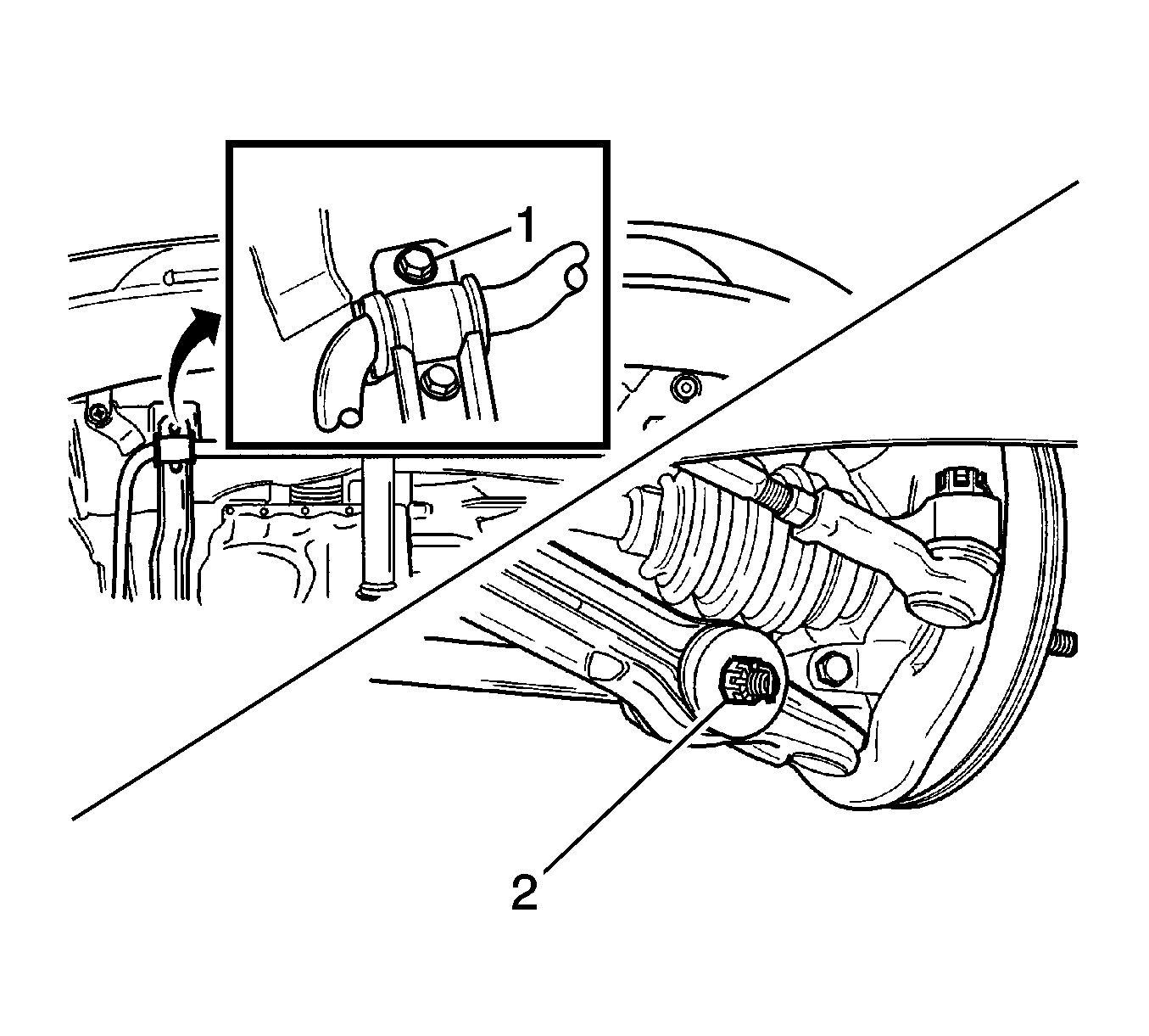
Tighten
Tighten the stabilizer bar castellated nut to 40-50 N·m (30-36 lb ft).
Tighten
Tighten the stabilizer bar mounting bar to 33-53 N·m (24-39 lb ft).
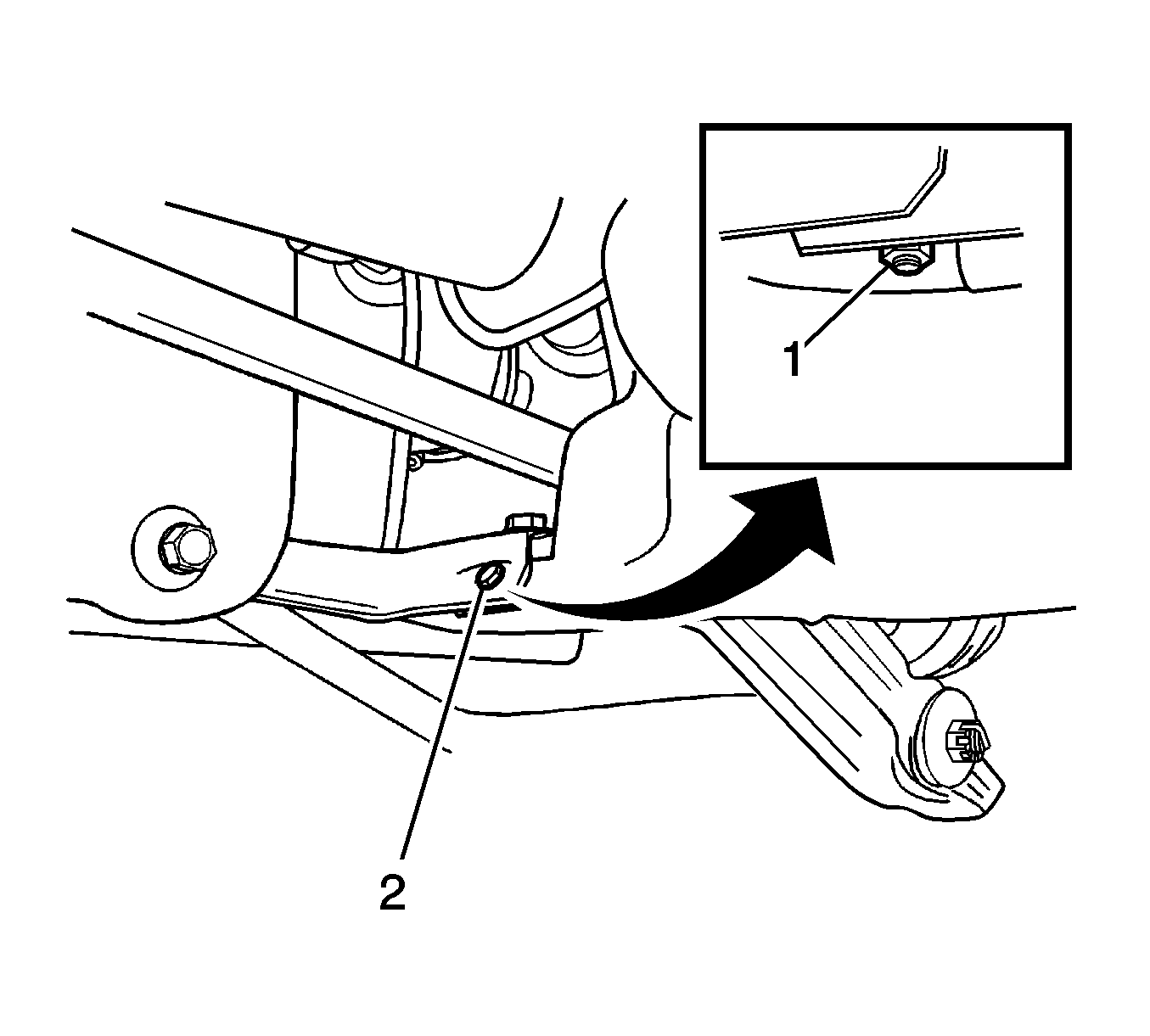
Tighten
Tighten the front longitudinal member bolt to 10-14 N·m (7-10.5 lb ft).
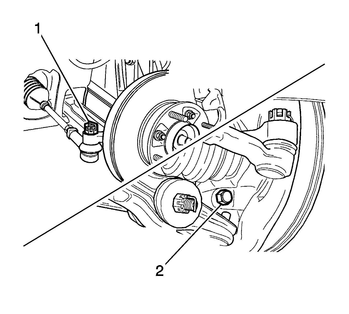
Tighten
Tighten the control arm stud nut to 50-870 N·m (36-52 lb ft).
Tighten
Tighten the tie rod end castellated nut to 35-55 N·m (25-41 lb ft).
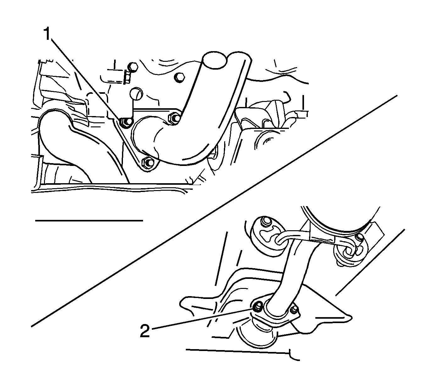
Tighten
Tighten the front exhaust pipe nuts on the muffler pipe side/exhaust manifold side to 25-35 N·m (18-25 lb ft).
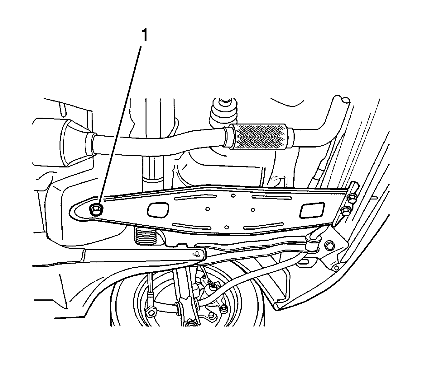
Tighten
Tighten the transaxle under cover bolts to 35-55 N·m (25-41 lb ft).
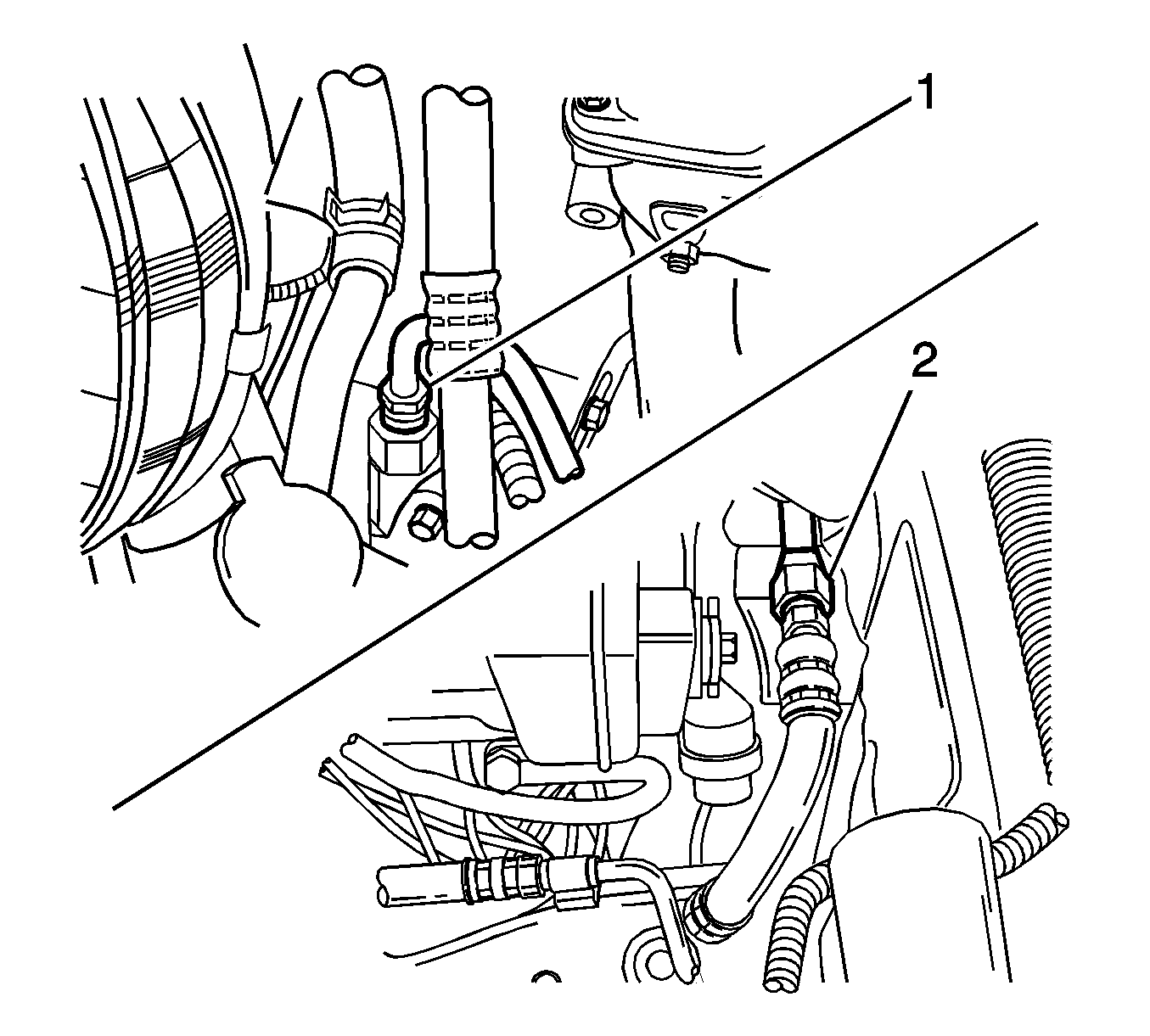
Tighten
| • | Tighten the power steering pump pressure pipe nut to 36-50 N·m (26-36 lb ft). |
| • | Tighten the power steering pump pressure pipe fitting to 21-35 N·m (15-25 lb ft). |
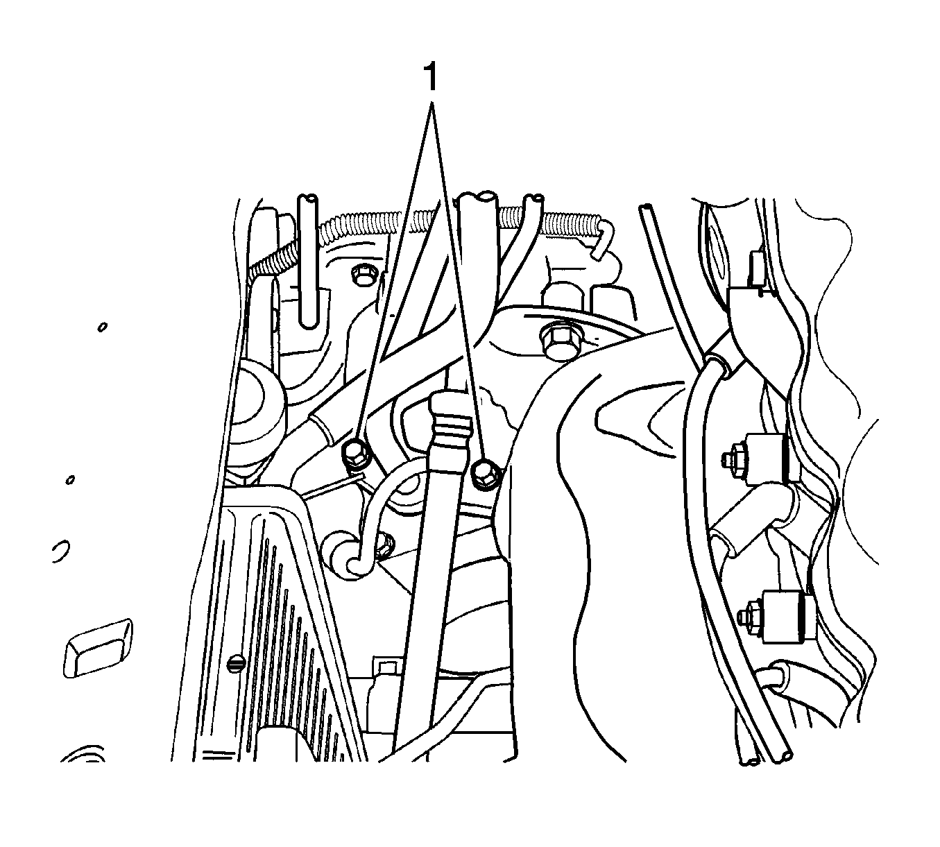
Tighten
Tighten the air conditioning low/high pressure pipe bolts to 23 N·m (17 lb ft).
Tighten
Tighten the radiator bolt to 4-5 N·m (35-44 lb in).
Tighten
Tighten the cooling fan bolt to 4-5 N·m (35-44 lb in).
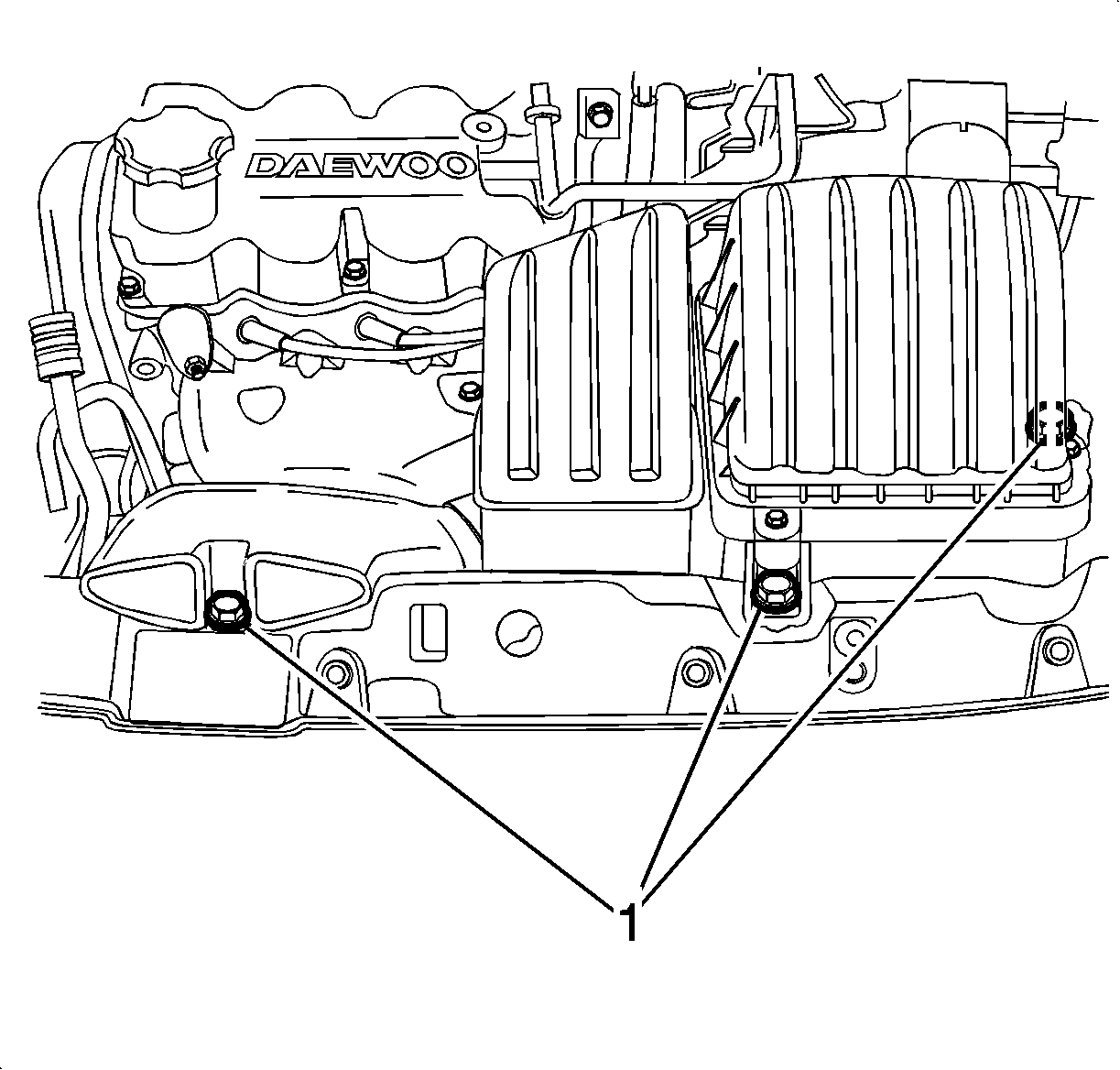
Tighten
Tighten the snorkel bolt to 7-9 N·m (62-80 lb ft).
