Special Tools
| • | EN46567 (DW 110-020-A) Engine Assembly Support Fixture |
| • | DT 47535 (DW 260-230) Transaxle Remover/Installer Support or equivalent |
Removal Procedure
- Remove the air cleaner assembly. Refer to Air Cleaner Assembly Replacement .
- Remove the battery and battery tray. Refer to Battery Replacement .
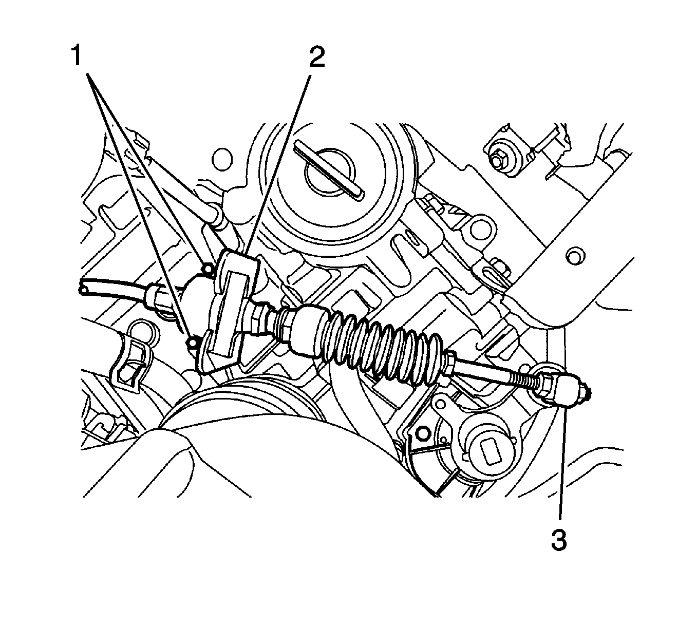
- Remove the select cable bracket bolts (1) and bracket.
- Remove the cable E-rings (2) and nut (3).
- Separate the select cable.
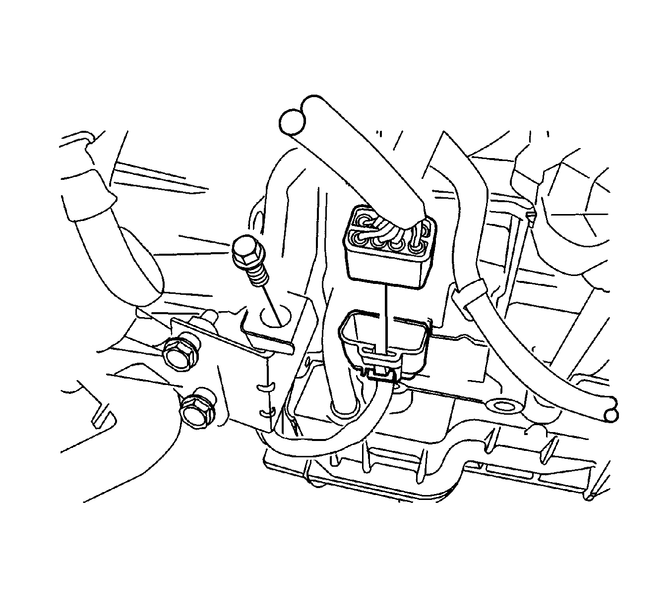
- Remove the engine wiring harness bending strap.
- Disconnect the connectors.
- Remove the radiator lower hose bracket retaining bolt.
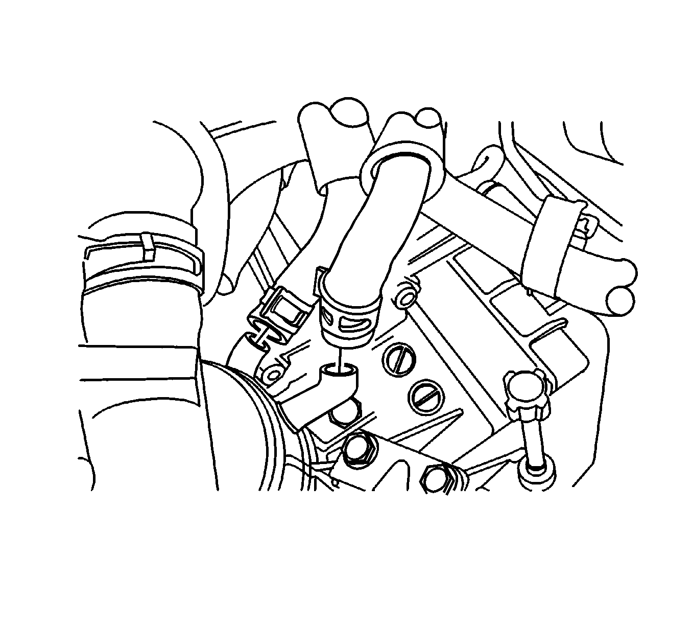
- Disconnect the clamps and oil cooler hoses.
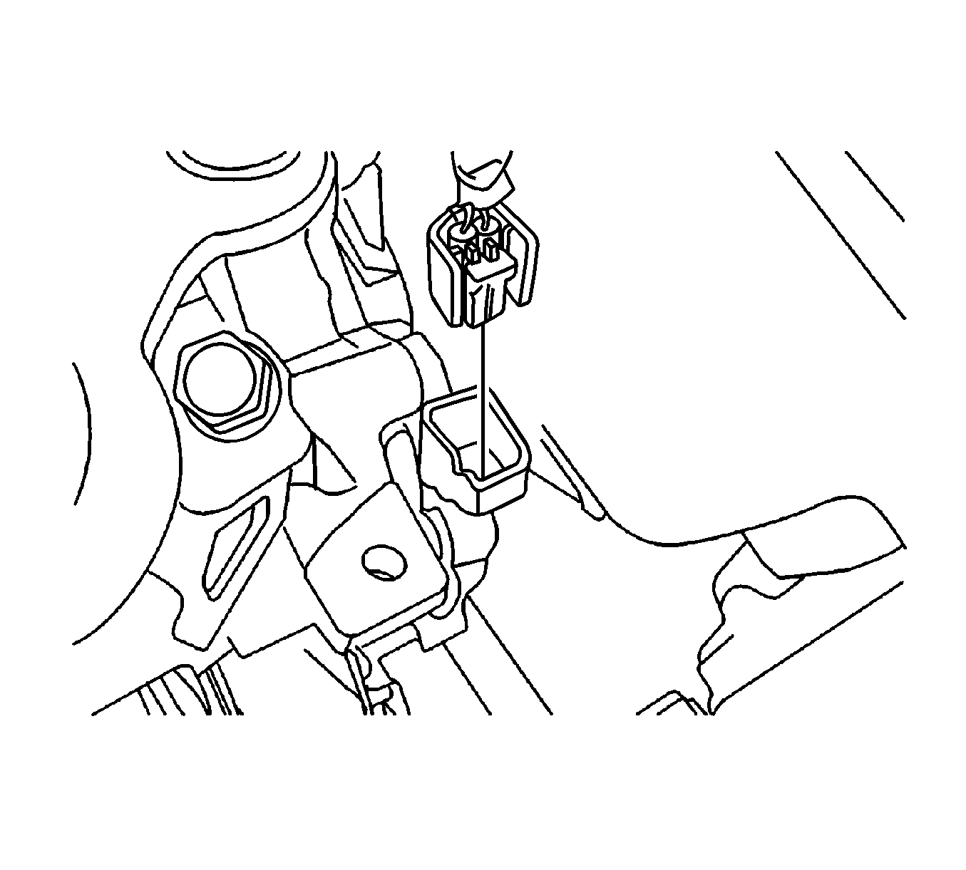
- Disconnect the turbine sensor.
- Remove the starter motor. Refer to Starter Motor Replacement .
- Remove the air inlet grille panel weatherstrip.
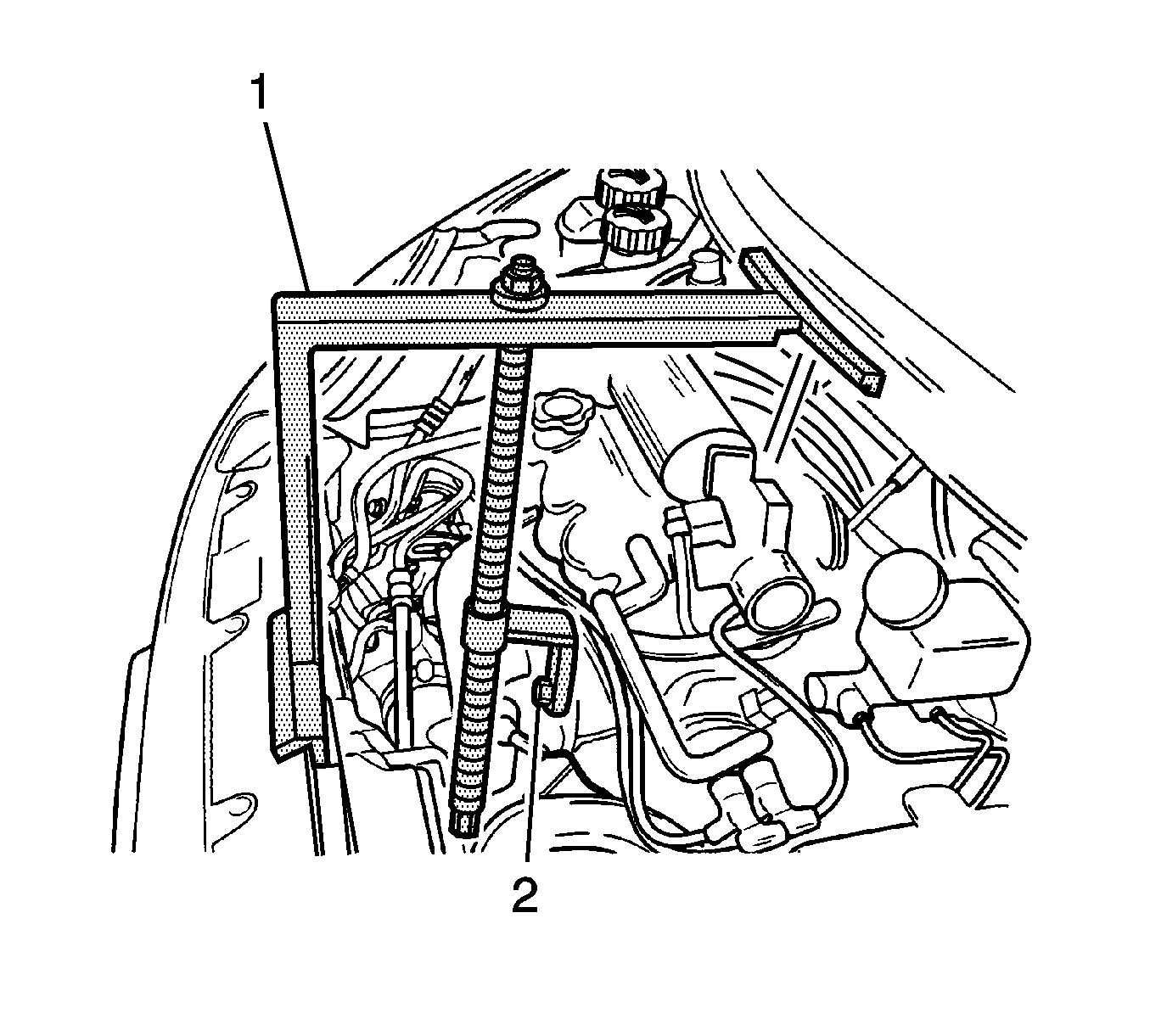
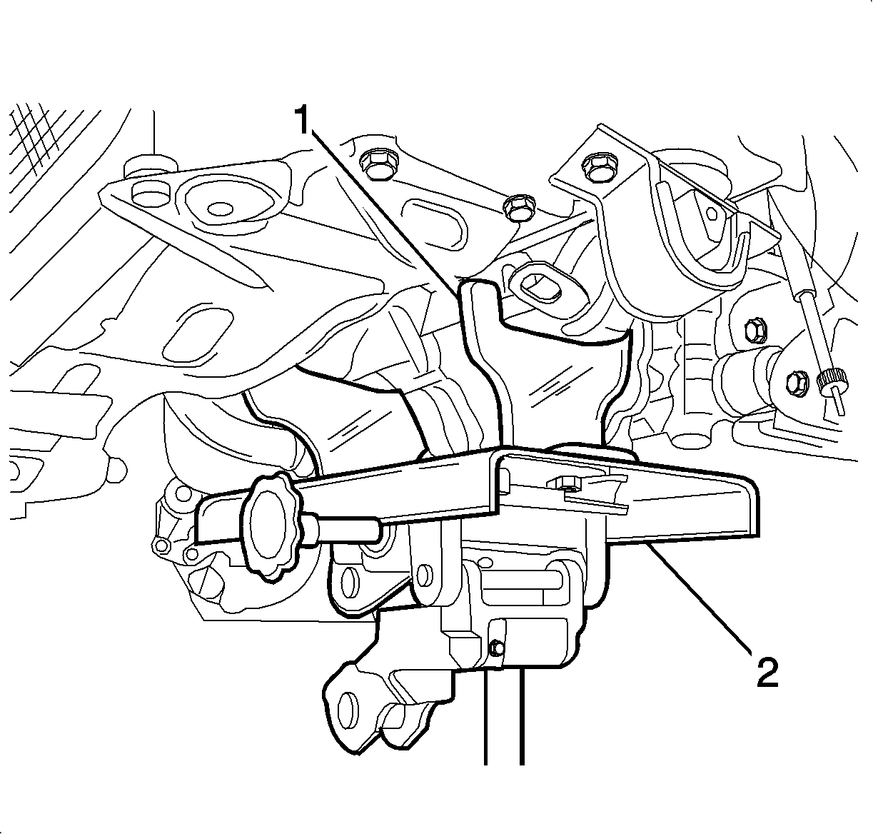
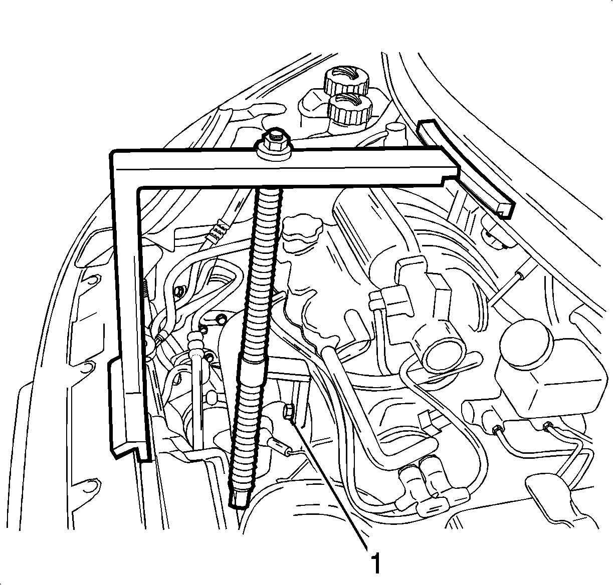
- Position the EN46567 (1), on the air inlet grille panel and the front upper panel.
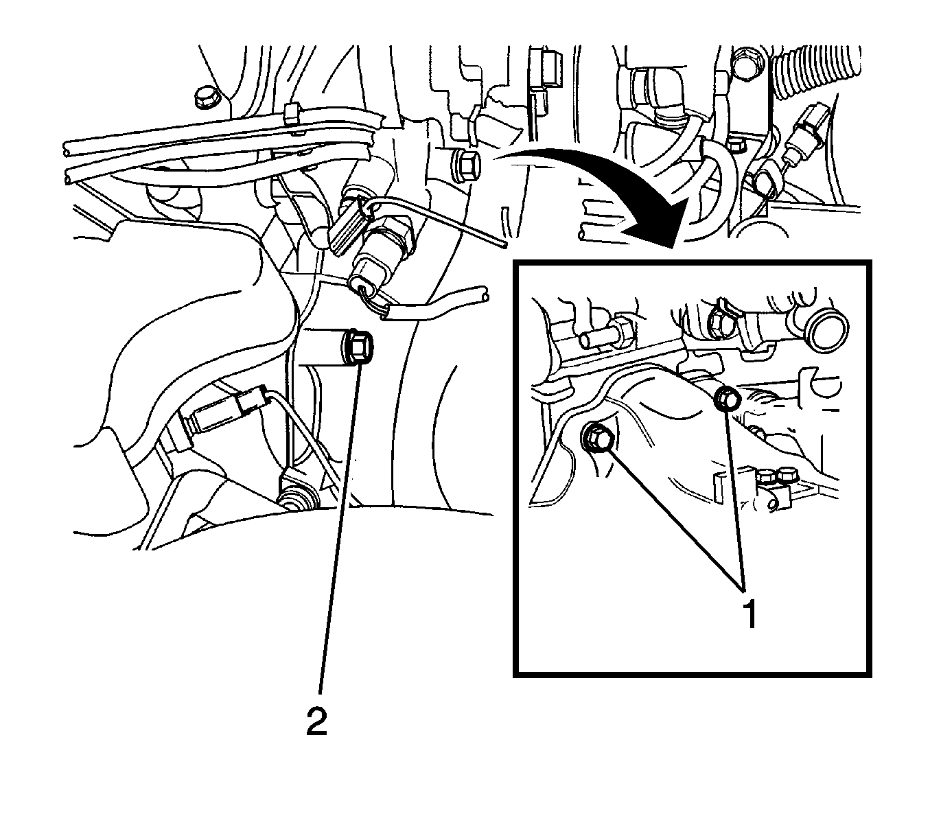
- Tighten the engine fixture joint bolt after removing the exhaust manifold bolt.
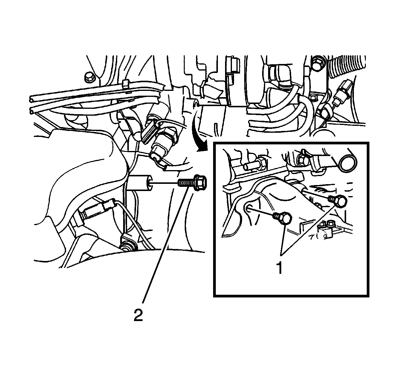
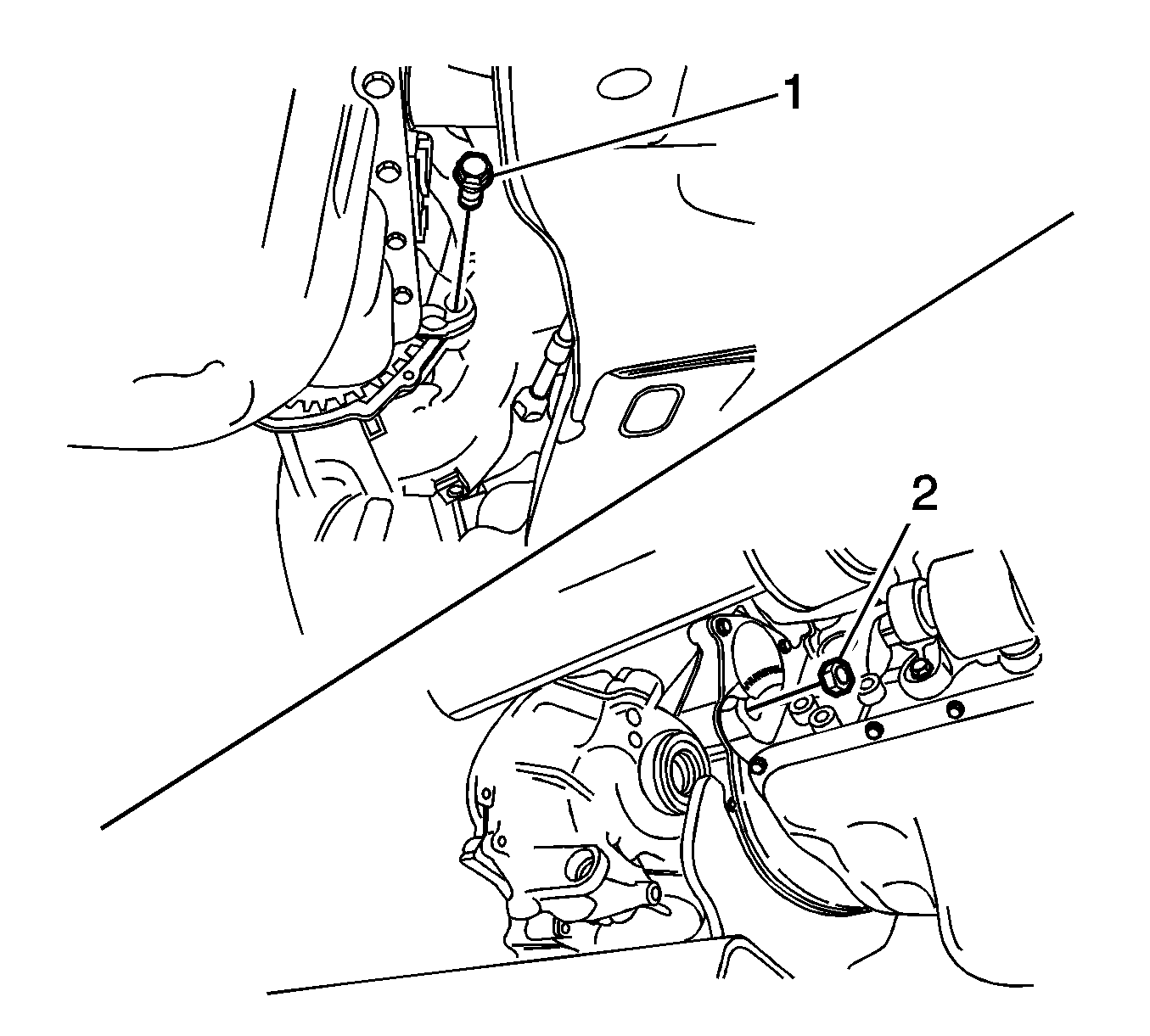
- Remove the transaxle upper exhaust manifold side bolt (1) and the thermostat housing side bolt (2).
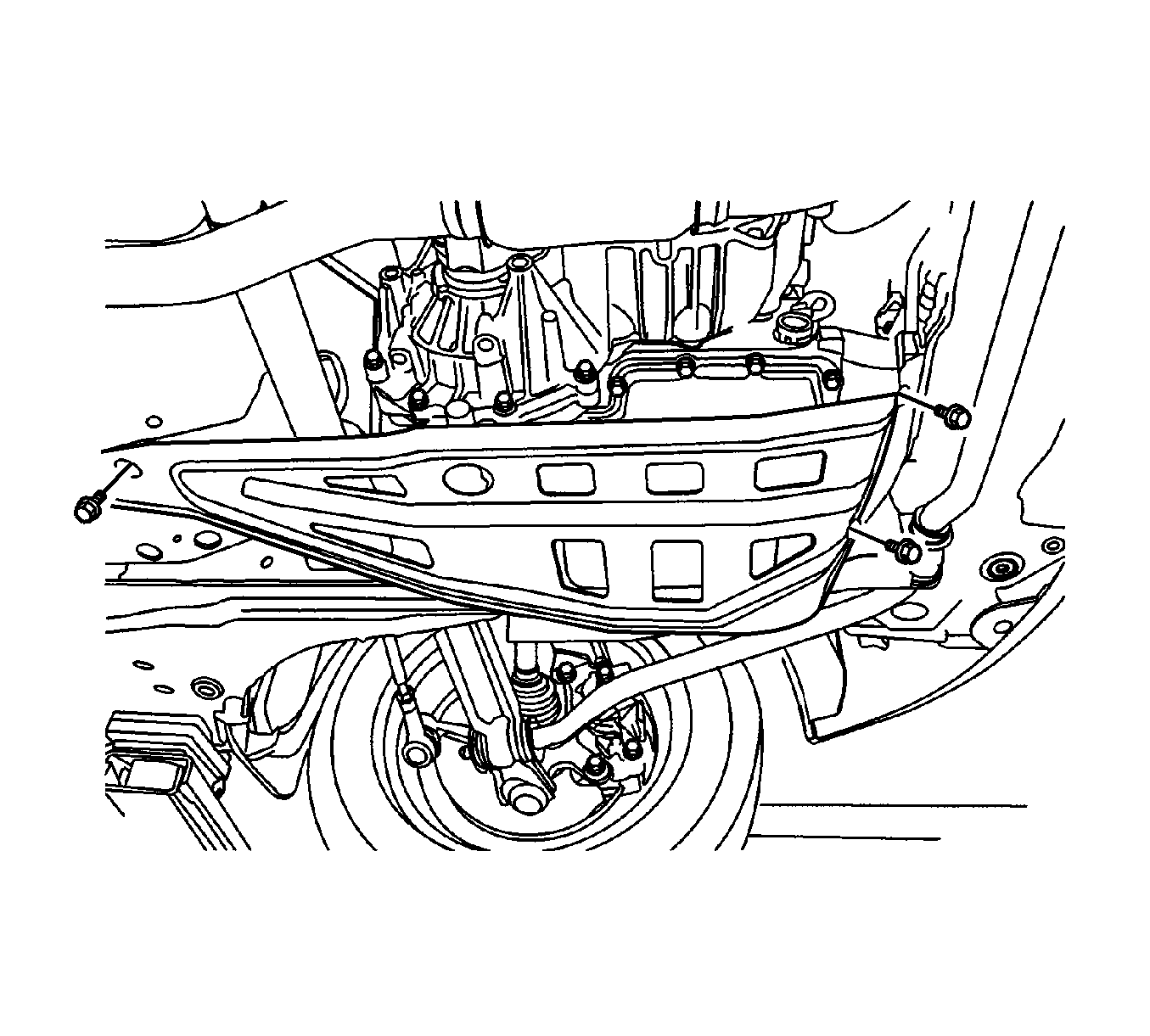
- Remove the transaxle under cover bolts and the transaxle under cover.
- Disconnect the vehicle speed sensor.
- Remove the front tires and wheels.
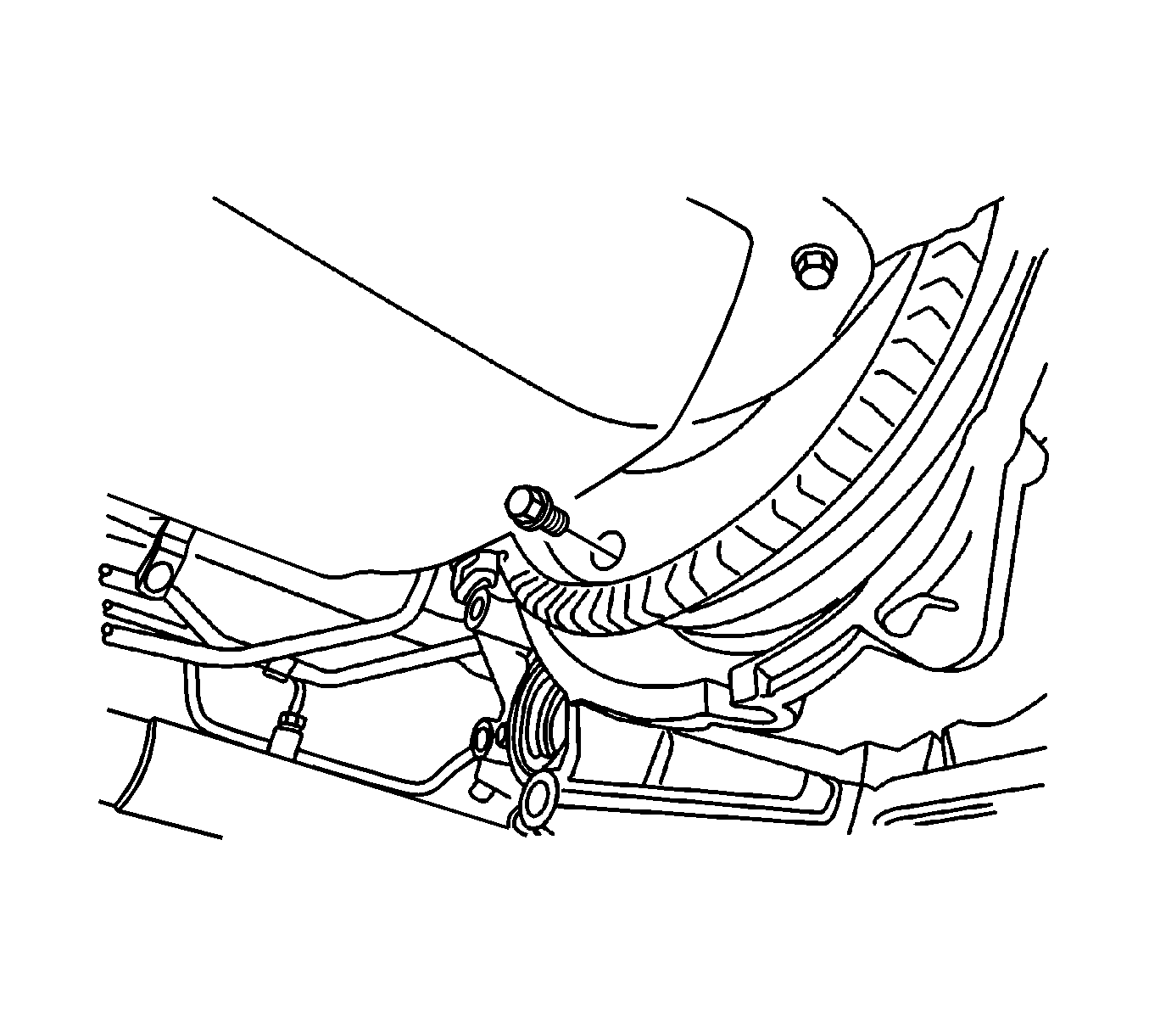
- Remove the drain plug and drain the fluid.
- Remove the front under longitudinal frames and stabilizer. Refer to Stabilizer Shaft Replacement .
- Remove the drive axle, only from the transaxle side. Refer to Front Drive Axle Inner Shaft Replacement .
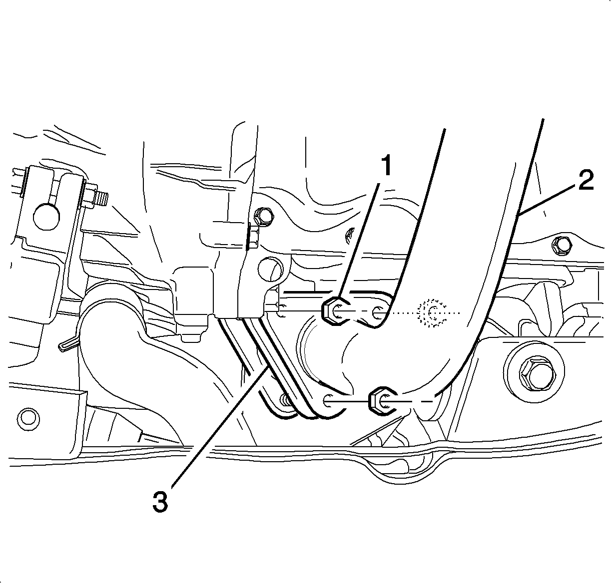
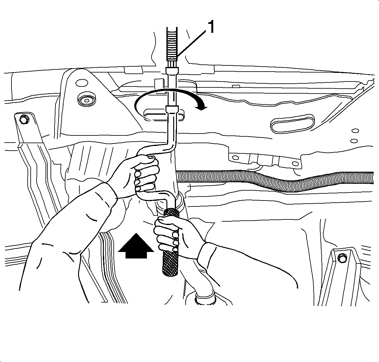
- Remove the front exhaust pipe nuts from the exhaust manifold side (1).
- Remove the gasket and separate the exhaust manifold pipe (3).
- Remove the front exhaust pipe (2).
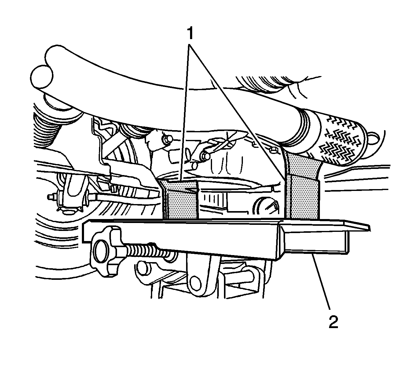
- Support the transaxle with DT 47535 (1).
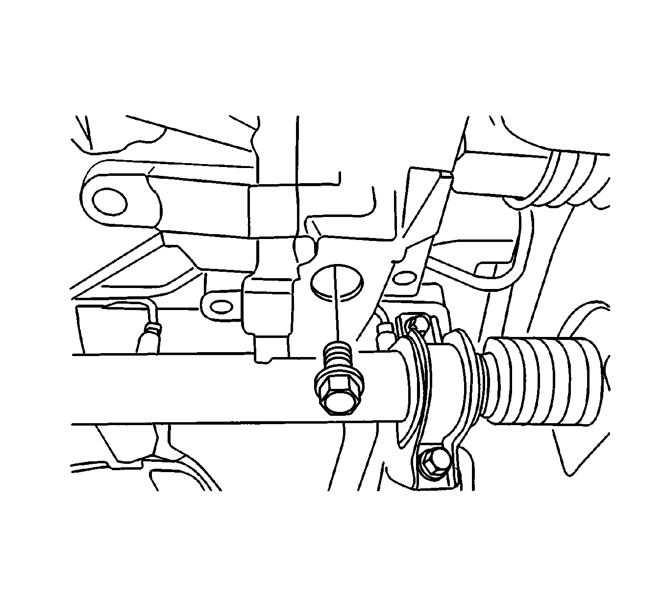
- Remove the transaxle lower bolt (1) and nut (2).
- Remove the torque converter bolts.
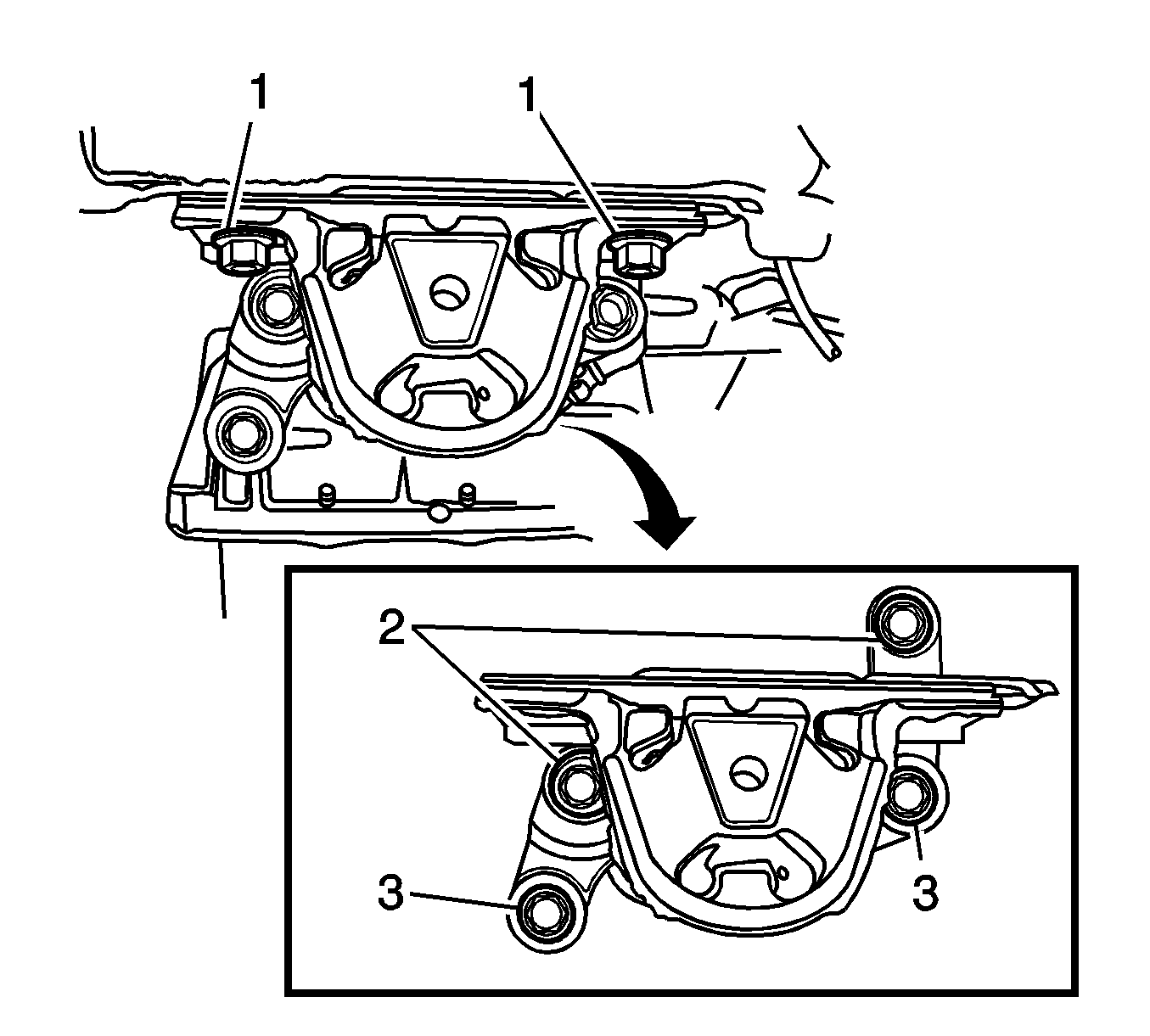
- Remove the transaxle mount bolts (1-3) mount.
- Lower the transaxle assembly slowly by adjusting the jack (2).
- Tilt the transaxle assembly by adjusting the jack.
- Remove the transaxle assembly by pulling and lowering it slowly.
- Support the engine to normal position using the EN46567 (1).
Caution: Refer to Battery Disconnect Caution in the Preface section.
Caution: While engine is operating, the exhaust system will become extremely hot. To prevent burns avoid contacting a hot exhaust system.
Caution: While engine is operating, the exhaust system will become extremely hot. To prevent burns avoid contacting a hot exhaust system.
Notice: Support the engine in the normal position when removing the transaxle. Damage to related parts can occur.
Important: If it is impossible to use the special tool, support the engine to normal position with the auto jack.
Installation Procedure
- Install the transaxle mounting bolts and mount.
- Install the torque converter bolts.
- Install the transaxle lower bolt (1) and nut (2).
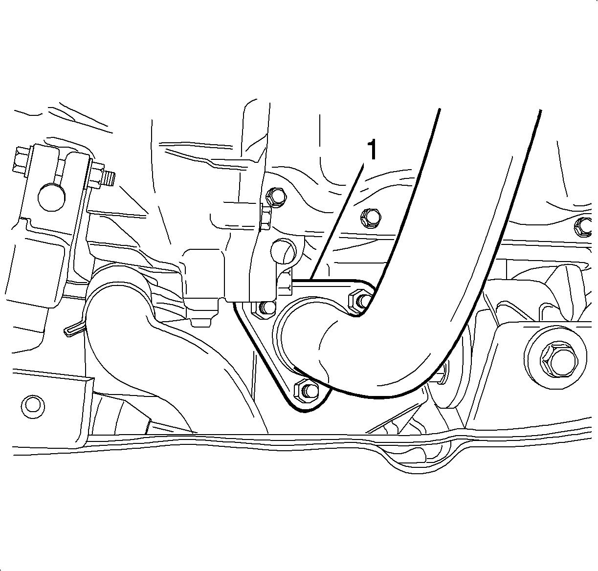
- Install the front exhaust pipe nuts (1).
- Install the drain plug (2).
- Refill recommended fluid to the proper level.
- Install the front under longitudinal frames and stabilizer. Refer to Stabilizer Shaft Replacement .
- Install the drive axle. Refer to Front Drive Axle Inner Shaft Replacement .
- Install the transaxle under cover.
- Connect the vehicle speed sensor connector.
- Install the transaxle upper exhaust manifold side bolt (1) and the thermostat housing side bolt (2).
- Remove the EN46567 (1).
- Install the air inlet grille panel weatherstrip.
- Install the starter motor.
- Connect the turbine sensor connector.
- Connect the clamps and oil cooler hoses.
- Install the radiator lower hose.
- Connect the wiring harness connectors.
- Install the wiring harness retainer.
- Install the select cable.
- Install the E-ring (2) and nut (3).
- Install the selectable bracket bolts (1) and bracket.
- Install the battery and battery tray. Refer to Battery Replacement .
- Install the air cleaner assembly. Refer to Air Cleaner Assembly Replacement .
Notice: Refer to Fastener Notice in the Preface section.

Tighten
| • | Tighten the transaxle mounting bolts (1, 2) to 50 N·m (37 lb ft). |
| • | Tighten the transaxle mounting bolts (3) to 37 N·m (27 lb ft). |

Tighten
Tighten the torque converter bolts to 19 N·m (14 lb ft).

Tighten
Tighten the bolt and nut to 60 N·m (44 lb ft).
Tighten
Tighten the front exhaust pipe nuts on the exhaust manifold side to 30 N·m (22 lb ft).

Tighten
Tighten the drain plug to 44 N·m (32 lb ft).
Specification
The classification is ESSO JWS3314.
Specification
The capacity is 4.78 L (5.05 qt).

Tighten
Tighten the transaxle under cover bolts to 45 N·m (33 lb ft).
Tighten
Tighten the bolts to 60 N·m (44 lb ft).

Tighten
Tighten the starter motor bolts 23 N·m (17 lb ft).


Tighten
Tighten the radiator lower hose bolt to 12 N·m (106 lb in).

Tighten
Tighten the bracket bolts to 20 N·m (15 lb ft).
