For 1990-2009 cars only
Adjust the valve clearance in the following procedures:
- Remove the air filter/resonator assembly and the relevant parts installed on the cylinder head cover.
- Remove the cylinder head cover hexagon bolts and remove the cover.
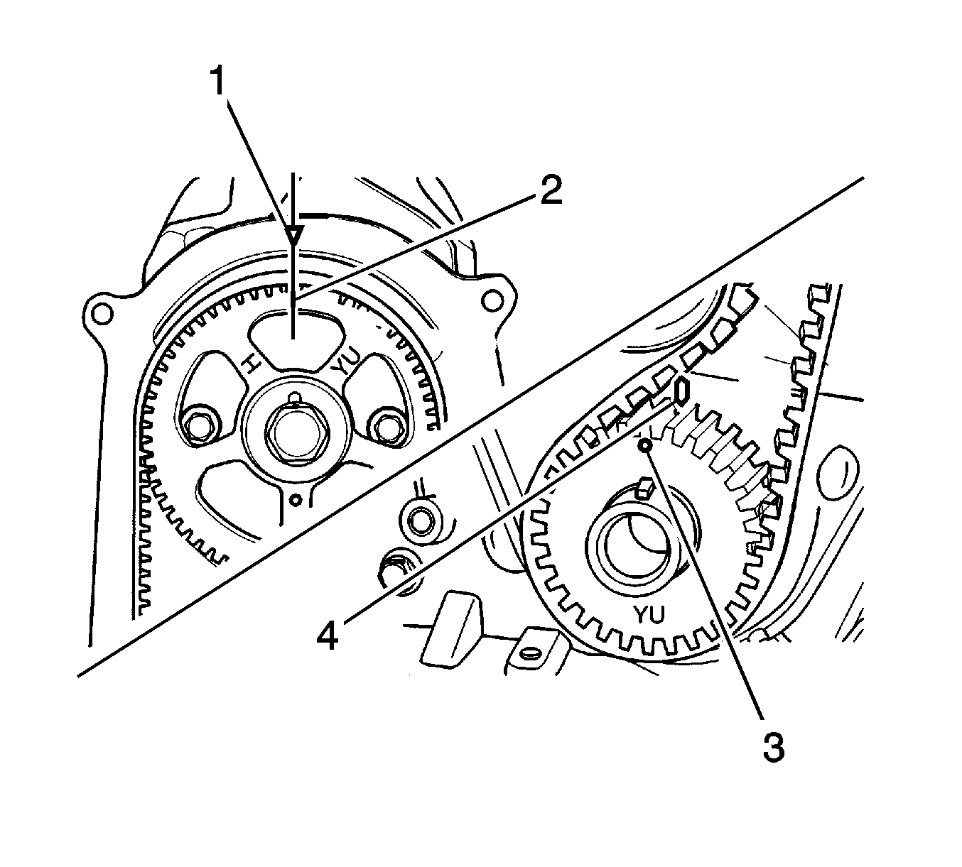
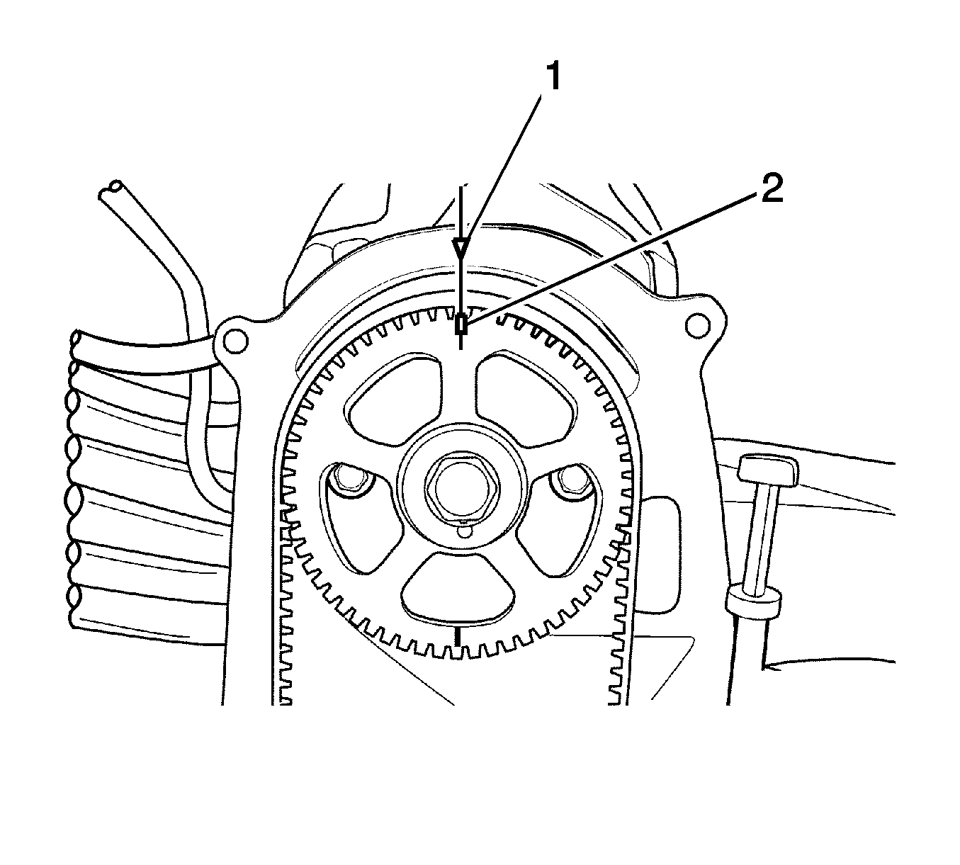
- Turn over the crankshaft to make No. 1 cylinder match with the compression top dead center. When the camshaft sprocket notch (2) is aligned with the timing belt rear cover triangle pointer (1), and the crankshaft sprocket point (3) is aligned with the oil pump housing point (4), the compression top dead center is on the ignition sequence for No. 1 cylinder.
- Check the valve clearance for No. 1 cylinder compression top dead center. Refer to Cylinder Compression Check Specifications in Engine Mechanical Specifications .
- When the valve clearance check of No. 1 cylinder compression top dead center is complete, position No. 1 cylinder on the exhaust, top dead center, while rotating the crankshaft in a 360-degree arc. When the camshaft sprocket point (2) is aligned with the timing belt rear cover triangle pointer (1), the exhaust top dead center is on the ignition sequence for No. 1 cylinder.
- Check the valve clearance for the No. 1 cylinder exhaust top dead center. Refer to Cylinder Compression Check Specifications in Engine Mechanical Specifications .
- Check and adjust the valve clearance (a) using thickness gage.
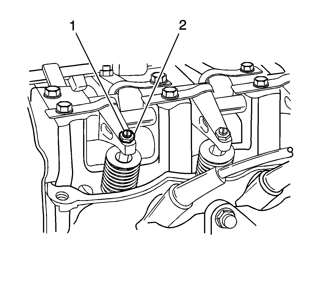
- When adjusting the valve clearance, loosen the adjust nut (2) and tighten or loosen the adjust rod (1) properly. Refer to Valve Clearance Specifications in Engine Mechanical Specifications .
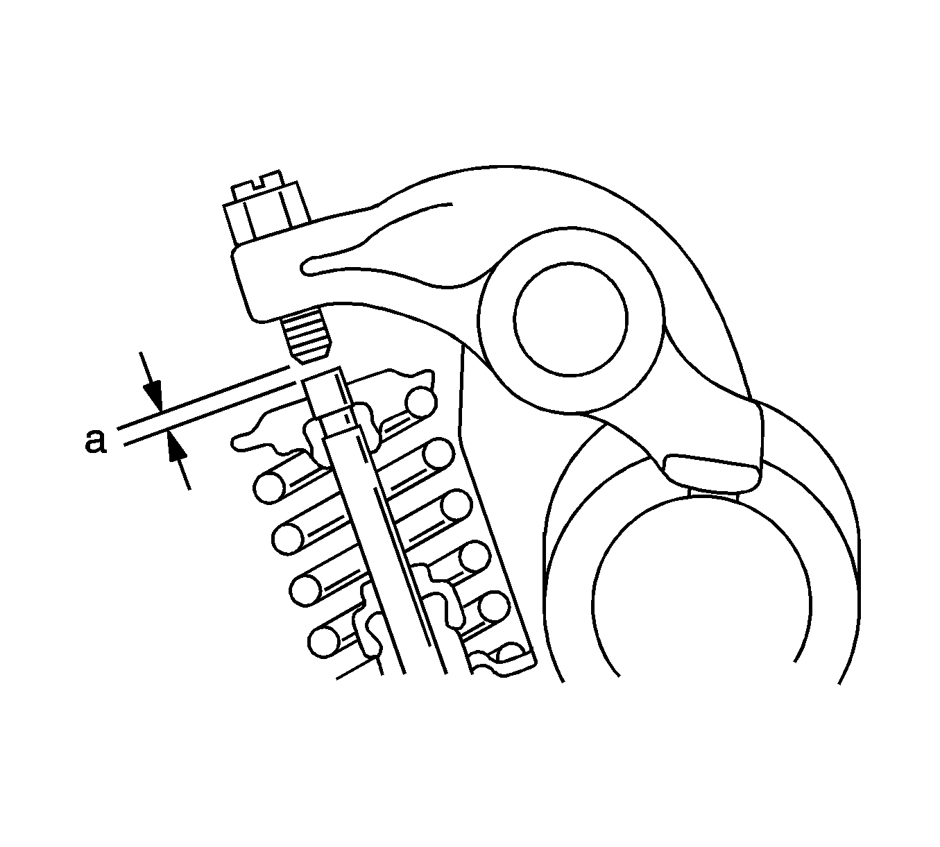
The measured value of valve clearance should meet the specified value. If not, adjust the valve clearance.
Important: In case of a hot engine, warm up the engine until the electric cooling fan begins to work and stop the engine to adjust the clearance with 20-30 minutes from there.
Valve Timing Procedure
- Check the valve timing.
- After removing the high headlamp, loosen the bolts (1) and remove the timing belt front upper cover (2).
- Turning the crankshaft clockwise twice, align the notch (2) on the crankshaft pulley (1), marked 0 , for the timing check on the timing belt front lower cover.
- Check if the notch (2) on the camshaft sprocket is aligned with the triangle pointer (1) on the timing belt rear cover.
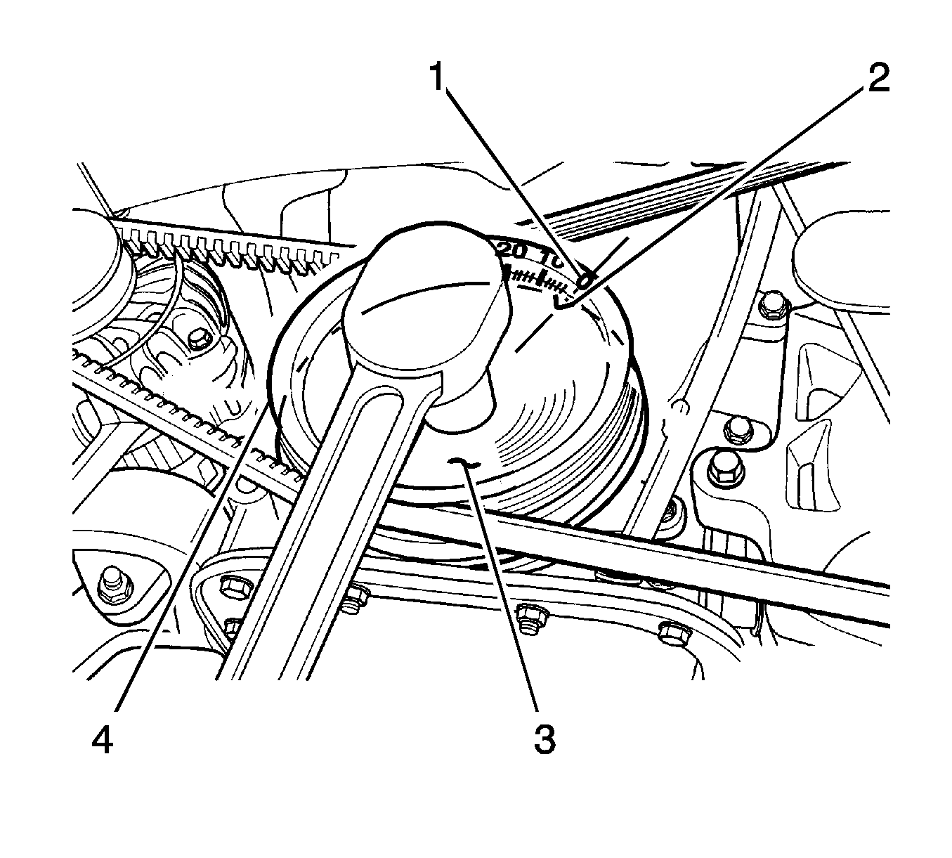
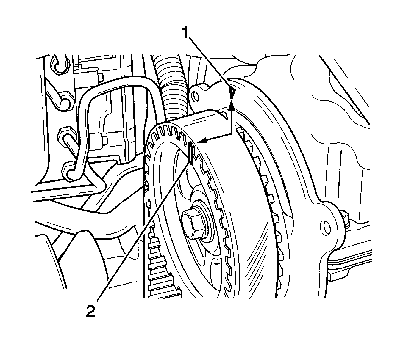
Important: Notch (2) should be aligned with pointer (1) to set the valve timing normally.
Valve Timing Adjustment Procedure
- Adjust the valve timing.
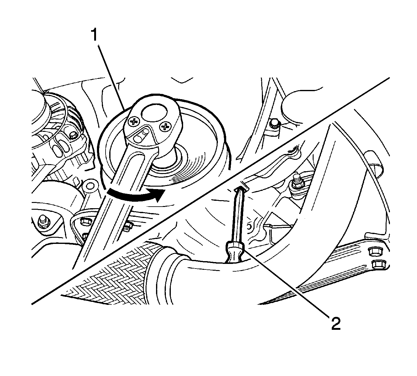
- Loosen the bolt and remove the timing belt pulley (1). In loosening the bolt, use the driver (2) in the picture as shown.
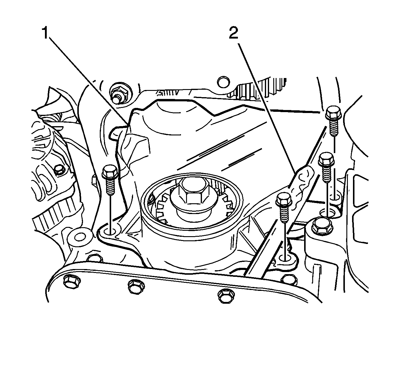
- Remove the oil level gage guide tube (2) and the timing belt front lower cover (1).
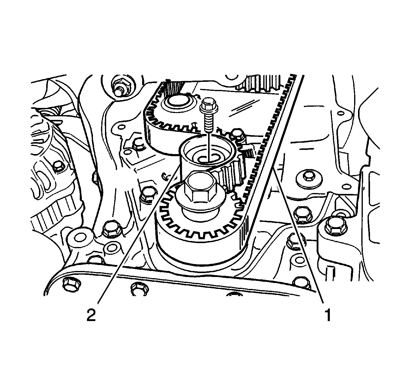
- Remove the timing belt tensioner (2) and the timing belt (1).
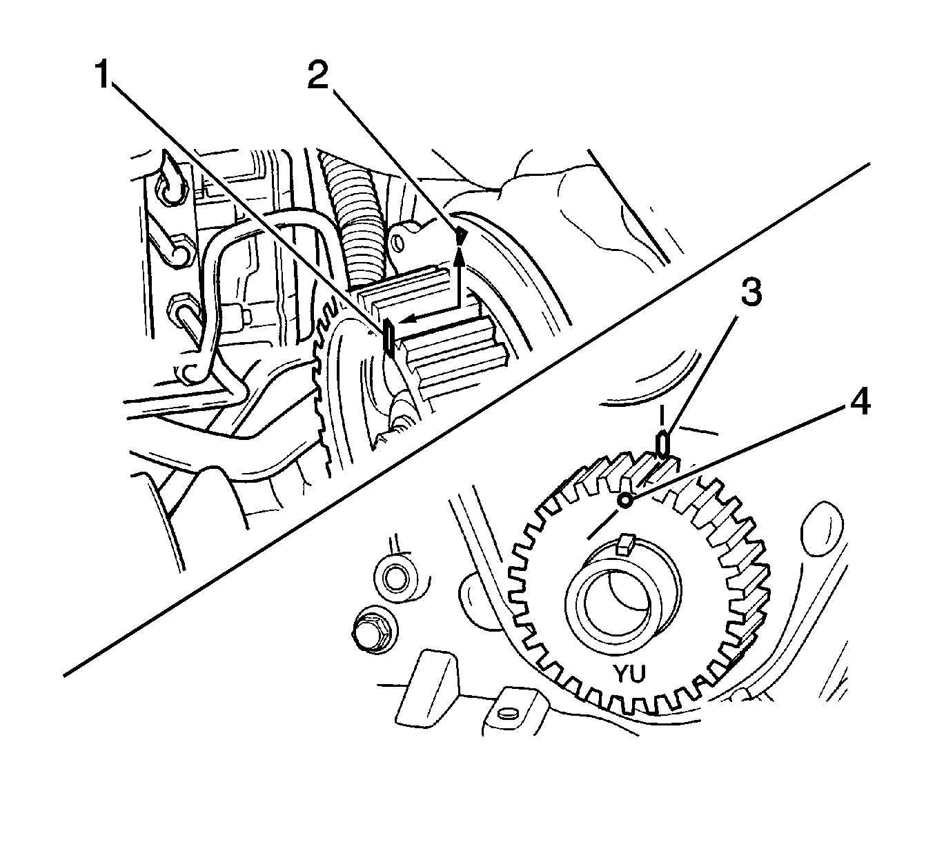
- Using the bolt, turn the crankshaft clockwise to align the mark (4) on the crankshaft sprocket with the pointer (3) on the oil pump housing. Then, turn the camshaft to align the notch (1) with the pointer (2).
- Install the timing belt (1) and the tensioner (2).
- Turn the crankshaft twice clockwise; align the mark (3) with the pointer (4) and tighten the tensioner bolt to 15-23 N·m (11-17 lb ft).
- Install all removed parts.
Notice: Refer to Fastener Notice in the Preface section.
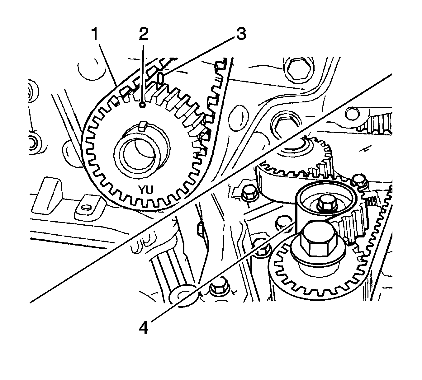
Important: Do not tighten the tensioner bolt completely.
