For 1990-2009 cars only
Removal Procedure
- Disconnect the battery negative cable.
- Disable the Supplemental Inflatable Restraints system. Refer to Disabling the SIR System, in SIR, in the 1999 C/K Service Manual.
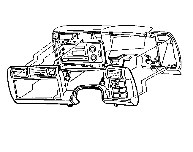
- Remove the lower trim panel screw.
- Remove the lower trim panel.
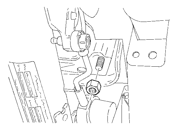
- Remove the nuts from the forward steering column bracket.
- Lower the steering column.
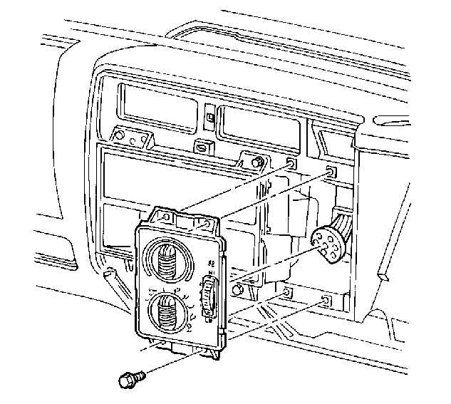
- Remove the 4WD switch from the instrument panel accessory trim plate.
- Disconnect the connector.
- Remove the screws along the top side of the instrument panel cluster.
- Remove the instrument panel accessory trim plate.
- Disconnect all of the connectors from the back of the instrument panel accessory trim plate.
- Remove the screws.
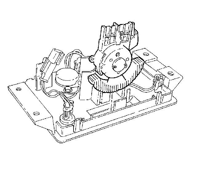
- Position the HVAC controls outward.
- Disconnect the vacuum connector from the HVAC controls.
- Remove the retaining screw.
- Remove the blower switch from the rear of the control bezel.
- Remove the retaining screw and remove the blower switch from the rear of the control bezel.
Caution: Unless directed otherwise, the ignition and start switch must be in the OFF or LOCK position, and all electrical loads must be OFF before servicing any electrical component. Disconnect the negative battery cable to prevent an electrical spark should a tool or equipment come in contact with an exposed electrical terminal. Failure to follow these precautions may result in personal injury and/or damage to the vehicle or its components.

Installation Procedure
- Install the blower switch to the control bezel with the retaining screw.
- Connect the vacuum connector to the HVAC controls.
- Install the HVAC controls to the instrument panel with the screws.
- Connect the harness connectors to the instrument panel accessory trim plate.
- Install the instrument panel accessory trim plate to the instrument panel.
- Install the instrument panel accessory trim plate screws.
- Connect the harness connector to the 4WD switch.
- Install the 4WD switch to the trim plate.
- Raise the steering column and install the nuts to the forward mounting bracket.
- Install the lower trim panel and the lower trim panel screws.
- Enable the SIR system. Refer to Enabling the SIR System, in SIR, in the 1999 C/K Service Manual.
- Connect the negative battery cable.
Tighten
Tighten the screws to 2 N·m (18 lb in).
Tighten
Tighten the screws to 2 N·m (18 lb in).
Tighten
Tighten the nuts to 30 N·m (22 lb ft).
Tighten
Tighten the screws to 1.9 N·m (18 lb in).
Tighten
Tighten the negative battery cable bolt to 17 N·m (13 lb ft).
