Steering Shaft, Lower Bearing, and Jacket - Assemble - Off Vehicle for Chevrolet Tahoe Limited 2000
Steering Shaft, Lower Bearing, and Jacket - Assemble - Off Vehicle Column Shift
Tools Required
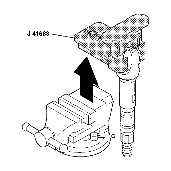
J 41688 Centering Sphere Installer

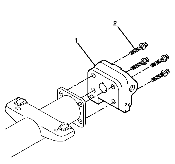
- Install the 4 TORX® screws (2) Into the steering column support assembly (1).
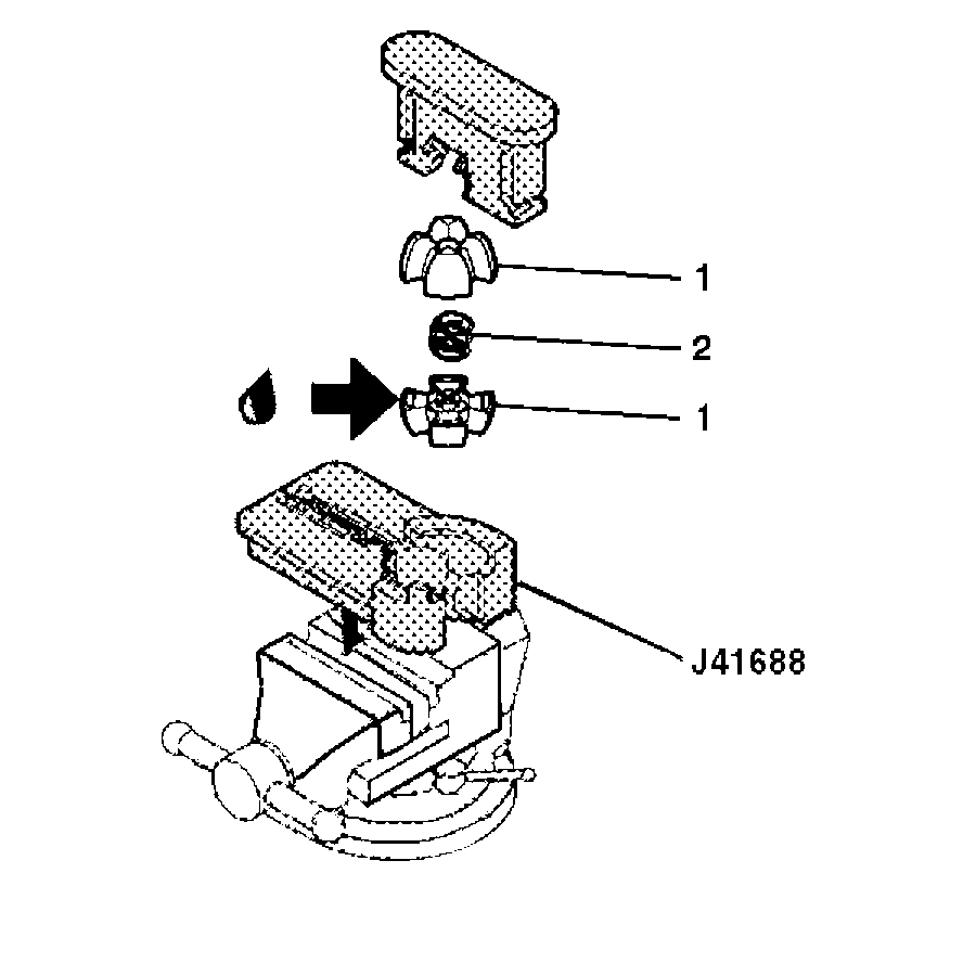
- Lubricate the centering sphere (1) with lithium grease.
- Install the centering sphere (1) and the joint preload spring (2) into J 41688 .
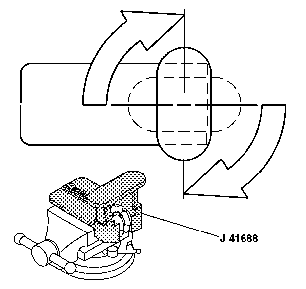
- Compress the centering sphere and joint preload spring. Rotate the driver 90 degrees in the clockwise direction until the arms lock in place.
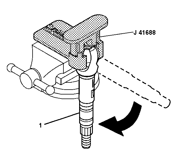
- Install the race and upper shaft assembly (1). Rotate the race and upper shaft assembly 90 degrees.
- Remove the race and upper shaft assembly with J 41688 . Rotate the race and upper shaft assembly 90 degrees and remove.
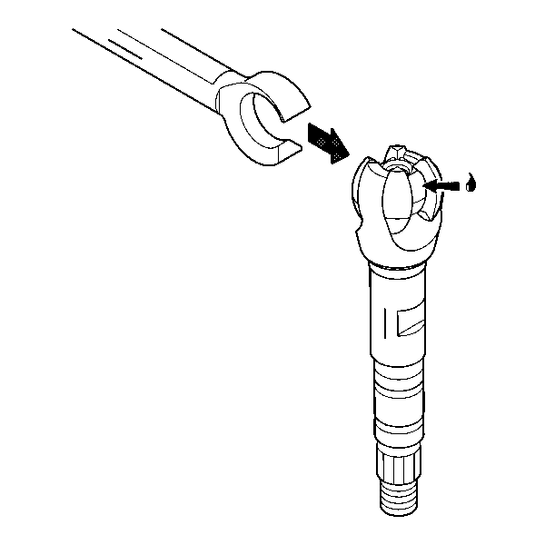
- Apply lithium grease to the race and upper shaft assembly.
- Install the lower shaft assembly to the race and upper shaft assembly using the marks from the disassemble procedure.
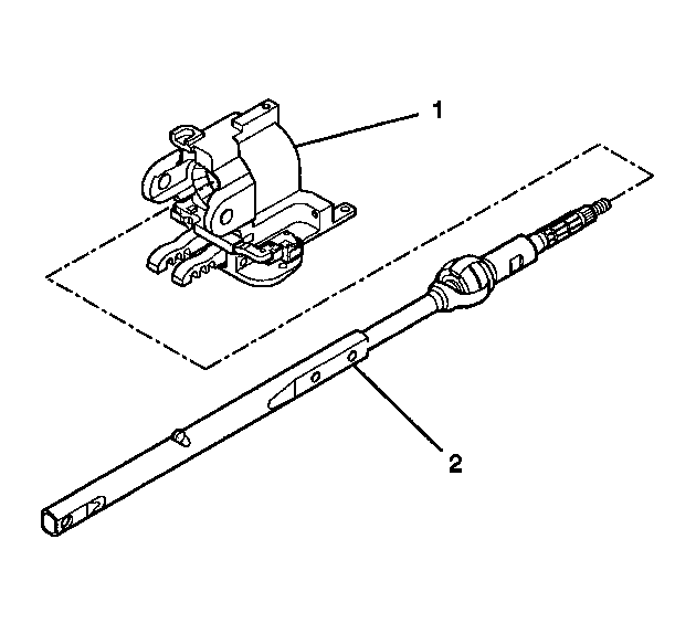
- Install the steering shaft assembly (2) into the steering column tilt head assembly (1).
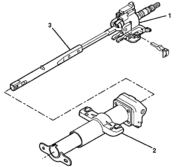
- Install the tilt head assembly (1) and the steering shaft (3) into the steering column jacket assembly (2).
- Install the 2 pivot pins onto the steering column support assembly.
- Stake the pivot pins.
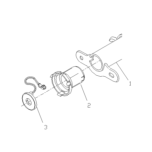
- Install the adapter and bearing assembly (2) into the steering column jacket assembly (1).
- Install the steering wheel speed sensor assembly (3).
- Install the linear shift assembly onto the steering column support assembly.
- Secure the linear shift assembly to the steering column assembly with the 3 flat head tapping screws.
- Install the automatic transmission shift lock control.
- Put the steering column in the NEUTRAL position.
- Adjust the automatic transmission shift lock control.
- Inspect the automatic transmission shift lock control.
- Install the turn signal and multifunction switch only. Refer to Turn Signal and Multifunction Switch Assembly - Assemble - Off Vehicle .
- Install the tilt spring assembly only. Refer to Tilt Spring - Assemble - Off Vehicle .
- Install the lock module assembly. Refer to Electronic Column Lock Module - Assemble - Off Vehicle .
Notice: Use the correct fastener in the correct location. Replacement fasteners must be the correct part number for that application. Fasteners requiring replacement or fasteners requiring the use of thread locking compound or sealant are identified in the service procedure. Do not use paints, lubricants, or corrosion inhibitors on fasteners or fastener joint surfaces unless specified. These coatings affect fastener torque and joint clamping force and may damage the fastener. Use the correct tightening sequence and specifications when installing fasteners in order to avoid damage to parts and systems.
Important: Replace the steering column support assembly (1) and the pivot pins if the steering column support assembly (1) and the pivot pins have been staked 3 times.
Tighten
Tighten the screws to 17 N·m (13 lb ft).
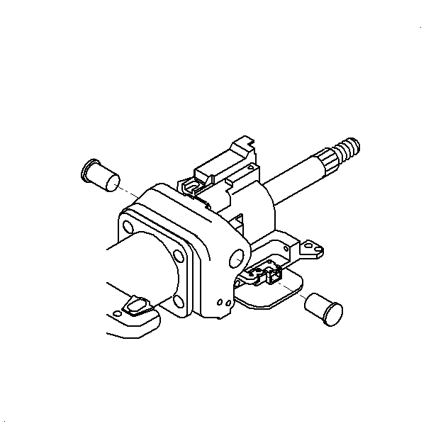
Important: Replace the steering column support assembly and the pivot pins if the steering column support assembly and the pivot pins have been staked 3 times.
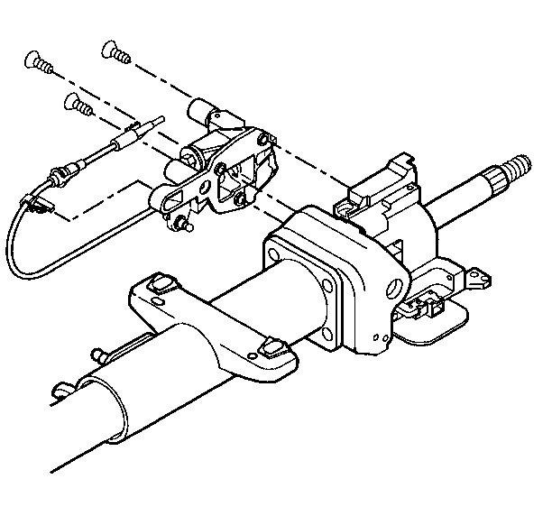
Move the linear shift assembly out of the PARK position to install the lower socket tapping screw.
Tighten
Tighten the 3 flat head tapping screws to 10 N·m
(89 lb in).
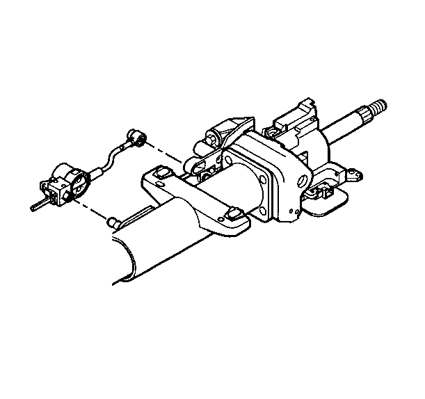
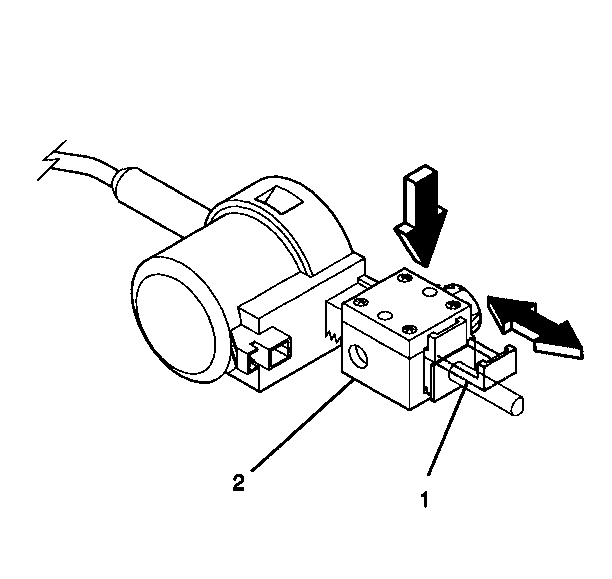
| 19.1. | Pull the tab (1) out on the block side (2) of the automatic transmission shift lock control. |
| 19.2. | Press on the adjuster block (2) to compress the internal adjuster spring to disengage the adjuster teeth. Slide the adjuster block as far away from the solenoid as possible. |
| 19.3. | Lock in place by pushing the tab (1) back in. |
| 20.1. | The automatic transmission shift lock control must lock the gear shift lever when it is put into the PARK position. |
| 20.2. | When the column is installed in the vehicle you will not be able to shift the gear shift lever out of the PARK position without pressing on the brake pedal. The solenoid will be energized. |
| 20.3. | Readjust if needed. |
Steering Shaft, Lower Bearing, and Jacket - Assemble - Off Vehicle Floor Shift
Tools Required
J 41688 Centering Sphere Installer
Notice: Use the correct fastener in the correct location. Replacement fasteners must be the correct part number for that application. Fasteners requiring replacement or fasteners requiring the use of thread locking compound or sealant are identified in the service procedure. Do not use paints, lubricants, or corrosion inhibitors on fasteners or fastener joint surfaces unless specified. These coatings affect fastener torque and joint clamping force and may damage the fastener. Use the correct tightening sequence and specifications when installing fasteners in order to avoid damage to parts and systems.
- Install the 4 TORX® screws (2) Into the steering column support assembly (1).
- Lubricate the centering sphere (1) with lithium grease.
- Install the centering sphere (1) and the joint preload spring (2) into J 41688 .
- Compress the centering sphere and joint preload spring. Rotate the driver 90 degrees in the clockwise direction until the arms lock in place.
- Install the race and upper shaft assembly (1). Rotate the race and upper shaft assembly 90 degrees.
- Remove the race and upper shaft assembly with J 41688 . Rotate the race and upper shaft assembly 90 degrees and remove.
- Apply lithium grease to the race and upper shaft assembly.
- Install the lower shaft assembly to the race and upper shaft assembly using the marks from the disassemble procedure.
- Install the steering shaft assembly (2) into the steering column tilt head assembly (1).
- Install the tilt head assembly (1) and the lower steering shaft (3) into the steering column jacket assembly (2).
- Install the 2 pivot pins onto the steering column support assembly.
- Stake the pivot pins.
- Install the adapter and bearing assembly (2) onto the steering column jacket assembly (1).
- Install the steering wheel speed sensor assembly (3).
- Install the tilt spring assembly only. Refer to Tilt Spring - Assemble - Off Vehicle .
- Install the turn signal and multifunction switch assembly only. Refer to Turn Signal and Multifunction Switch Assembly - Assemble - Off Vehicle .
- Install the lock module assembly. Refer to Electronic Column Lock Module - Assemble - Off Vehicle .
Important: Replace the steering column support assembly and the pivot pins if the steering column support assembly and the pivot pins have been staked 3 times.
Tighten
Tighten the screws to 17 N·m (13 lb ft).
Important: Replace the steering column support assembly and the pivot pins if the steering column support assembly and the pivot pins have been staked 3 times.
