For 1990-2009 cars only
Removal Procedure
- If RWD vehicle, remove the engine flywheel housing. Refer to Engine Flywheel Housing Replacement .
- Remove the engine front cover. Refer to Engine Front Cover Replacement .
- Remove the upper oil pan. Refer to Upper Oil Pan Replacement .
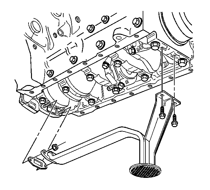
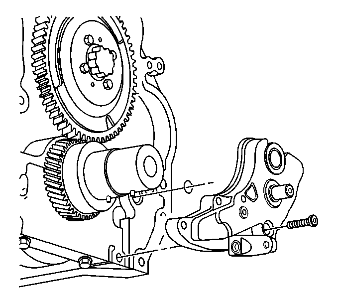
- Remove the oil pump pipe and screen assembly bolts and nuts.
- Remove the oil pump pipe and screen assembly.
- Remove the oil pump pipe and screen assembly gasket.
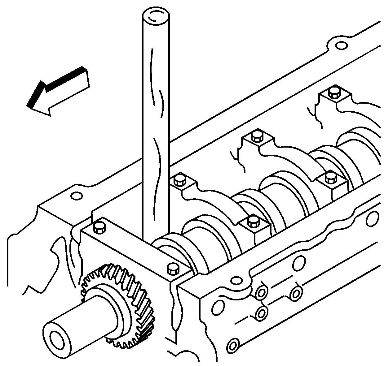
- Block the crankshaft from turning with a wooden handle.
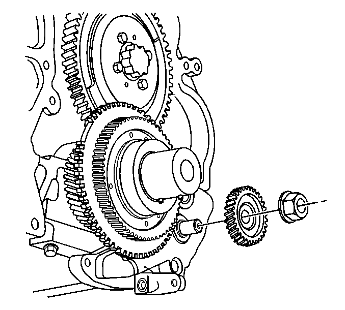
- Remove the oil pump driven gear nut.
- Remove the oil pump driven gear.
- Remove the oil pump drive gear and crankshaft reluctor assembly.
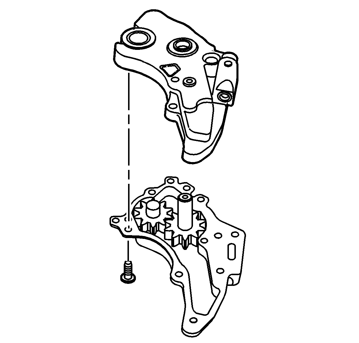
- Remove the 3 hex head and the 1 allen head bolt in order to remove the oil pump.
- Remove the oil pump.
- Remove the O-ring seal for the oil pump.
Important: Look for an "L" on the end of the oil pump shaft. If there is an "L" present, the nut and shaft have left hand threads. Service the nut accordingly.
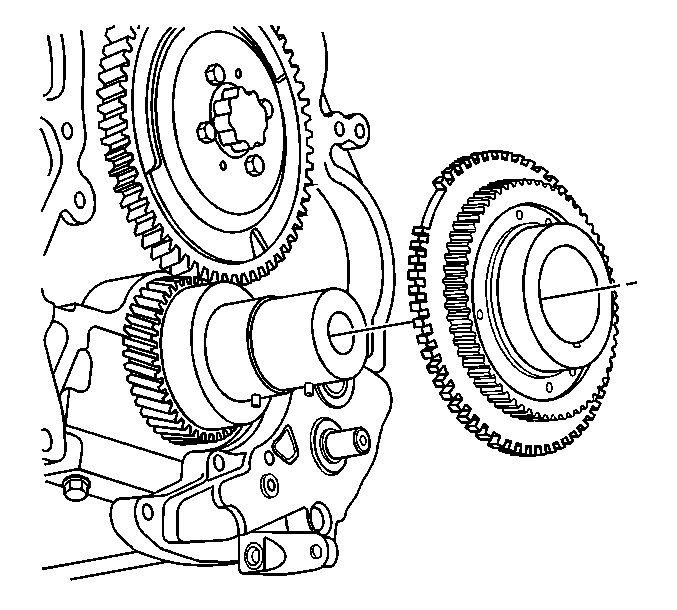
Important: Do not damage the crankshaft reluctor assembly. Do not remove the crankshaft reluctor to oil pump drive bolts.
| • | Use a brass drift. |
| • | Tap on the back as close to the center of the reluctor assembly. |
Inspection and Repair
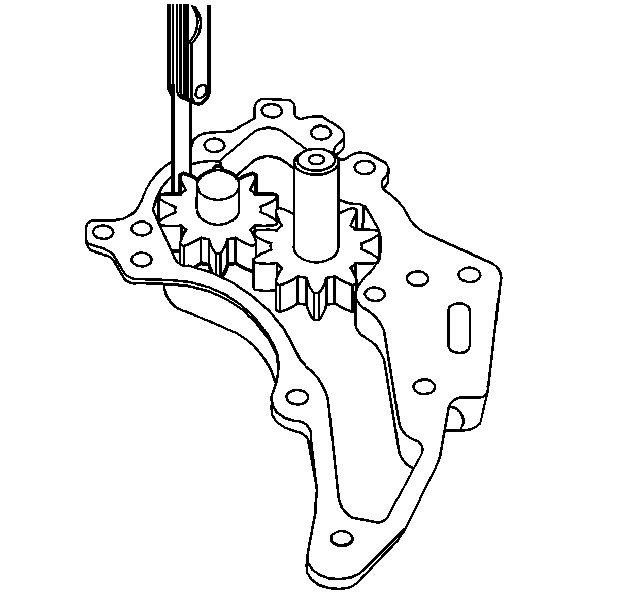
- Remove the oil pump gear cover bolts.
- Remove the oil pump gear cover.
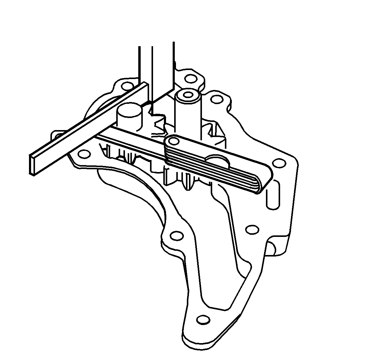
- Use a feeler gauge to measure the clearance between the gear teeth and the oil pump housing. The production clearance is 0.125-0.221 mm (0.0049-0.0087 in) and the service limit is 0.221 mm (0.0087 in).
- Replace the oil pump assembly if the clearance exceeds the service limit.
- Use a feeler gauge and a straightedge to measure the clearance between the side of the gear and the cover. The production clearance is 0.064-0.109 mm (0.0025-0.0043 in) and the service limit is 0.109 mm (0.0043 in).
- Replace the oil pump assembly if the clearance exceeds the service limit.
- Calculate the driven gear shaft to bushing clearance.
- Replace the oil pump assembly if the clearance exceeds the service limit.
- Install the oil pump gear cover to the oil pump assembly.
- Install the oil pump gear cover bolts.
| 7.1. | Measure the driven gear shaft outside diameter. The production specification is 19.947-19.960 mm (0.7853-0.7858 in) and the service limit is 19.86 mm (0.7819 in). |
| 7.2. | Measure the driven gear bushing inside diameter. The production value is 20 mm (0.7874 in). |
| 7.3. | Calculate the driven gear shaft to bushing clearance. The service limit is 0.14 mm (0.0055 in). |
Notice: Refer to Fastener Notice in the Preface section.
Tighten
Tighten the oil pump gear cover bolts to 21 N·m (15 lb ft).
Installation procedure
- Install a new O-ring seal for the oil pump.
- Install the oil pump.
- Install the oil pump bolts.
- Inspect the oil pump drive gear for wear.
- Replace the oil pump drive gear pin if worn.
- Install the oil pump drive gear and reluctor assembly to the crankshaft.
- Install the oil pump driven gear.
- Install the oil pump driven gear nut. Block the crankshaft from turning.
- If 4WD vehicle, install the oil pump pipe and screen gasket to the oil pump.
- If 4WD vehicle install the oil pump pipe and screen.
- If 4WD vehicle, install the oil pump pipe and screen assembly bolts and nuts.
- Install the engine front cover. Refer to Engine Front Cover Replacement .
- If RWD, install the engine flywheel housing. Refer to Engine Flywheel Housing Replacement .
- Install the upper oil pan. Refer to Upper Oil Pan Replacement .
Tighten
Tighten the oil pump bolts to 21 N·m (15 lb ft).
Tighten
Tighten the oil pump driven gear nut to 100 N·m (74 lb ft).
Tighten
| • | Tighten the oil pump pipe and screen assembly bolts to 25 N·m (18 lb ft). |
| • | Tighten the oil pump pipe and screen assembly nuts to 25 N·m (18 lb ft). |
