Your vehicle is equipped with wiring provisions for a 12-volt battery power supply. Refer to the following information when adding electrical accessories that will use the 12-volt power supply feeds connected to your vehicle's electrical system. The wiring harness is located in front of the glove compartment. The following information describes the fuse location and provides a wiring diagram to aid in connecting customer equipment. This wiring provision (SEO 9L4) may have been ordered for your Tahoe Special Service Package.
Electrical Connections
Notice: Before modifying or adding any wiring, be sure that it will work properly with your vehicle's wiring system. Because there are so many modifications that can be made for many different bodies and accessories, GM cannot take responsibility for any changes made. Such changes may not be covered by your GM Warranty. Have the work done by an experienced electrical technician.
All wiring must be properly protected by fuses, etc. and must be routed properly so that it will not be cut, pinched or rubbed by other parts of the vehicle. Do not route wiring in areas where it will be very hot. Be sure not to overload the vehicle's wiring, connectors and components. All added wire must be at least the same size as the wire being attached to for proper fuse protection.Installation Instructions -- 12-Volt Accessory Power Supply
- Disconnect the negative (-) battery cable at the battery. The negative (-) battery cable must be disconnected before the positive wiring lead is connected to the power accessory.
- Locate the power supply harness under the instrument panel near the passenger's side of the vehicle. The wire bundle consists of the pink ignition (IGN) , orange battery (BAT) and black negative (NEG) wire feeds.
- Remove the tape to release the wire bundles from the power supply harness.
- Remove the 40 amp MegaFuse that is taped to the wire bundle. Set aside for installation, after equipment wiring is complete.
- Prepare the wires that are to be used to connect the power accessory. Do not remove the unused wires. Tape unused wires back in their original position under the instrument panel.
- Complete the wiring installation of the customer added accessory with additional wire required for the specific electrical accessory power connection. The wire gauge, 12 gauge (3.0 mm), should be the same as the wiring of the installed harness.
- The ignition must be turned to LOCK or ACCESSORY prior to attaching the cables to the battery, or serious damage to the Vehicle Control Module (VCM) may result.
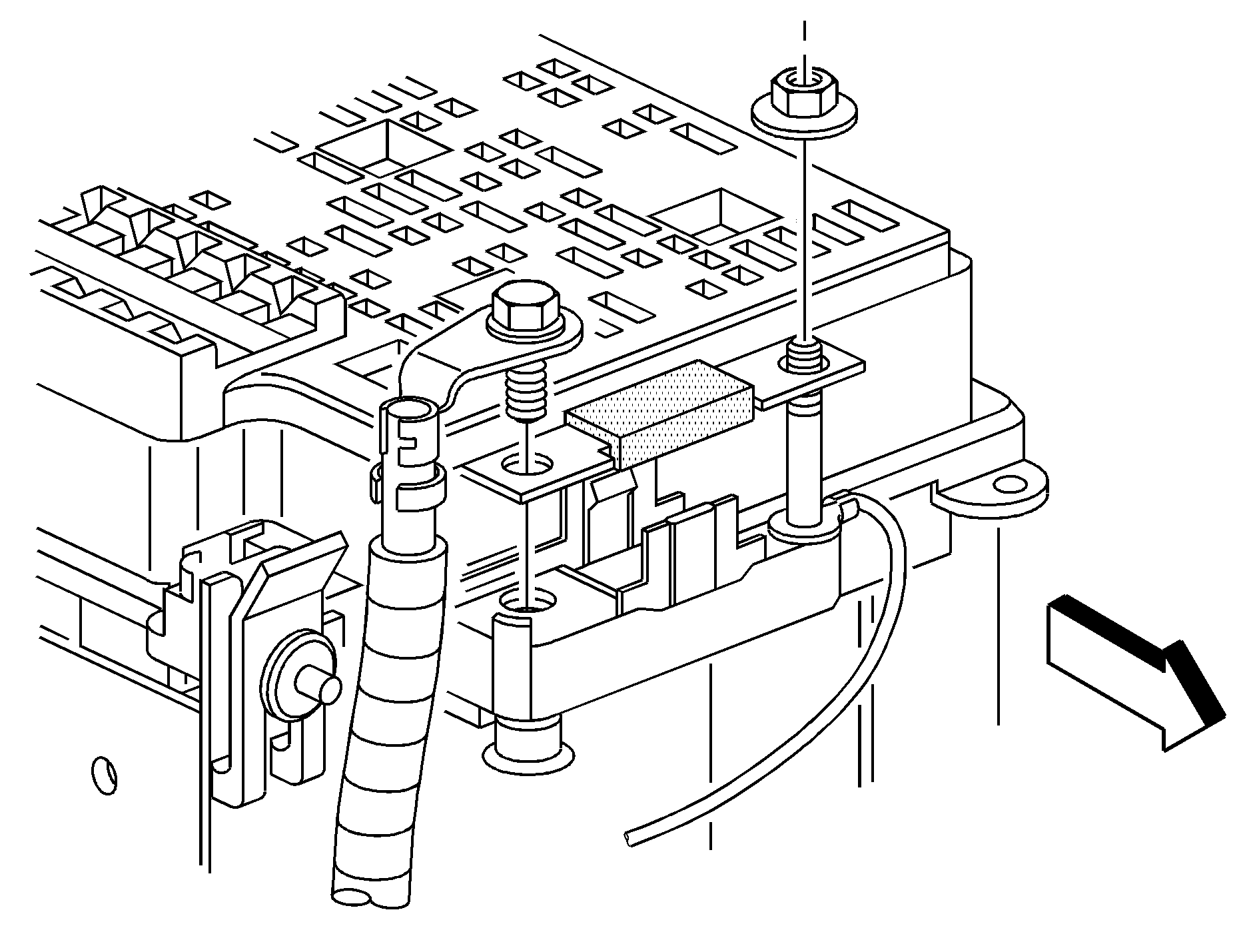
- Disconnect the positive (+) battery cable at the underhood power distribution center. Remove the nut from the 8 mm stud (see illustration).
- Install the 40 amp MegaFuse (from Step 4) in the front holder on the underhood power distribution center over the stud. Reinstall the positive (+) battery cable with the mounting screw through the MegaFuse terminal. Replace the 8 mm nut on the stud. Torque both the nut and screw to 1.3-2.7 lb.-ft (6-12 N·m).
- Reconnect the negative (-) battery cable to the battery. Torque the bolt to 12.5 lb-ft. (17 N·m).
- Reset the clock time and radio pushbuttons as desired.
The windshield wiper switch and the radio must be turned off before attaching cables to the battery.
Underhood Power Distribution Center

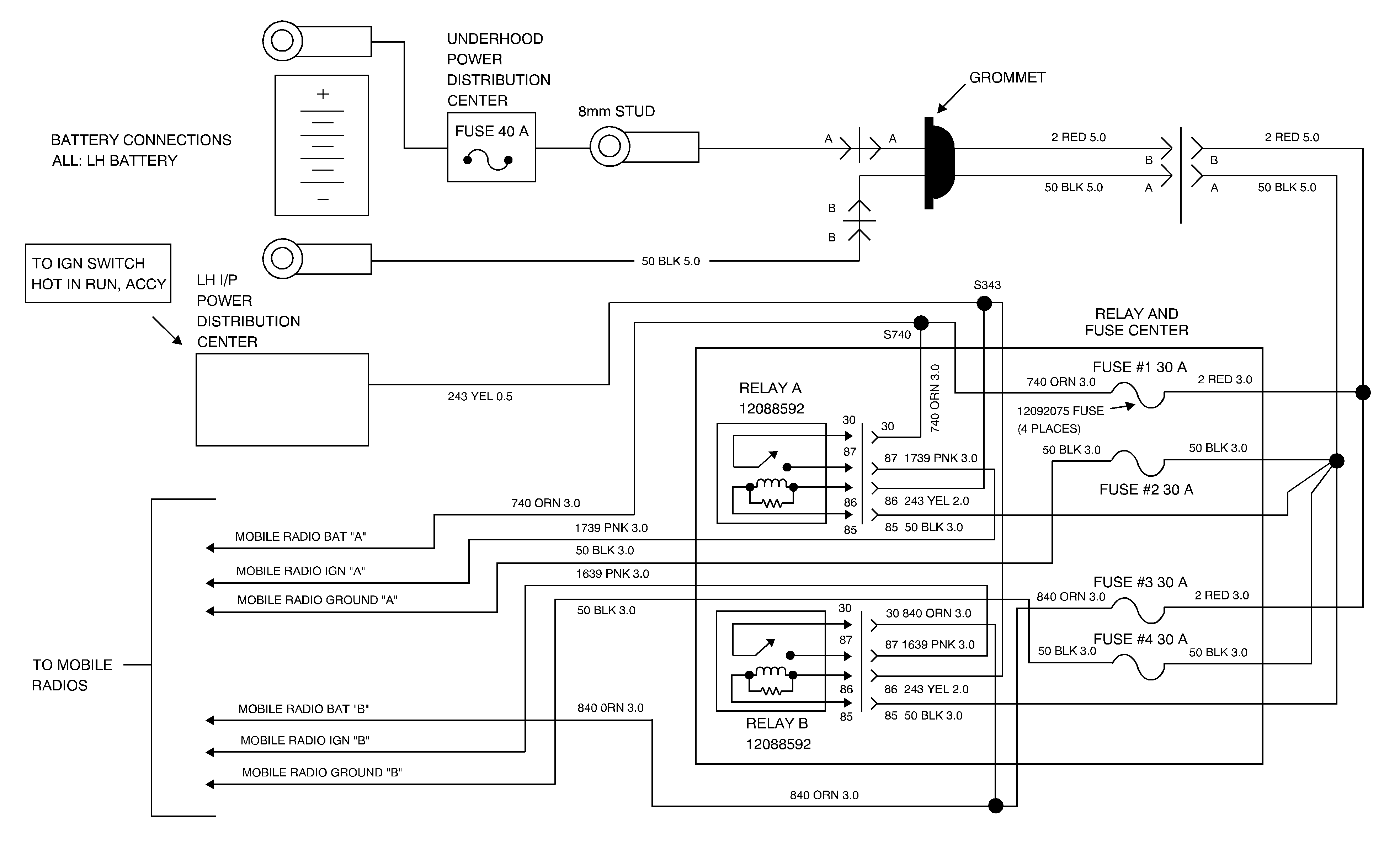
The IGN A and IGN B connections have voltage supplied and are hot when the ignition is turned to ACCESSORY or RUN (pink color wire).
The BAT A and BAT B connections have voltage supplied and are hot at all times (orange color wire).
The combined electrical load of IGN A and BAT A must not exceed 21 amps (250 watts). Additionally, the combined electrical load of IGN B and BAT B must not exceed 21 amps (250 watts). The combined electrical load of all circuits must not exceed 28 amps (340 watts).
Servicing Relays and Fuses
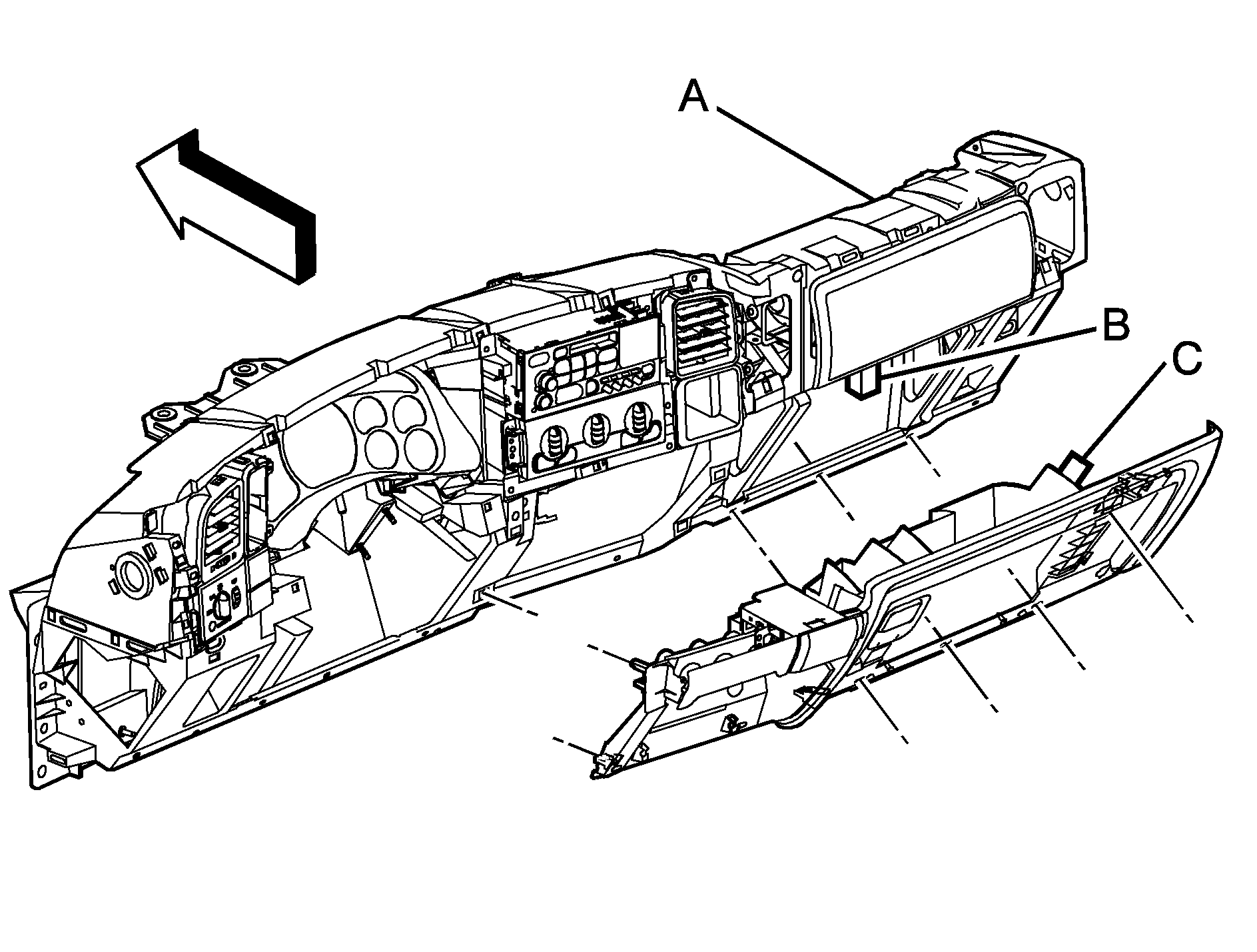
Exploded View of Instrument Panel

Instrument Panel
Relay and Fuse Center
Stop Tab
The following information tells you how to access your vehicle's relay and fuse center for checking and replacing fuses.
The fuse and relay center is located behind the instrument panel storage compartment. Remove contents from the storage tray. Push the right end of the tray inward to allow the stop tab to clear the compartment opening. Set the tray down gently toward the floor. It will hang from the hinge.
Additional access to the relay and fuse center can be gained by removing the center from the mounting bracket. Lift the lock tab on the bottom away from the bracket, then slide the center down the bracket about 0.39 inches (10 mm) until it can be lifted away.
Then, using a screwdriver, remove the relay and fuse center cover by lightly expanding the spring clips on each side of the cover. Replace the 30 amp mini fuse with a 30 amp mini fuse. Use a fuse puller if your vehicle has one. Replace a relay with a GM Part No. 12088592 relay, or equivalent.
After servicing the center, reinstall the relay center to the bracket. Engage the D slots, then push upward until the lock tab drops in place.
Reinstall the storage tray into the compartment by lifting it into the instrument panel. Push in on the right side to let the stop tab pass through the opening.
Wiring Provisions -- 12-Volt Battery Power

