Battery power is supplied through a 30 amp fuse to a wiring harness located in the roof. Power is controlled with a switch located on the instrument panel. The customer or vehicle upfitter must complete the installation to an added accessory such as an emergency beacon lamp.
Maximum rated electrical load is 21 amps (250 watts). The added electrical requirements must not exceed 21 amps (250 watts). Running the accessory for long periods of time with the engine off may run the battery down.
Installation Instructions -- Emergency Vehicle Roof Panel Lamp
Wiring to the accessory can be done by either directly connecting the wire in the roof to the accessory (Option A) or by using Wiring Harness Package part number 12150250 obtained from GM Service Parts (Option B).

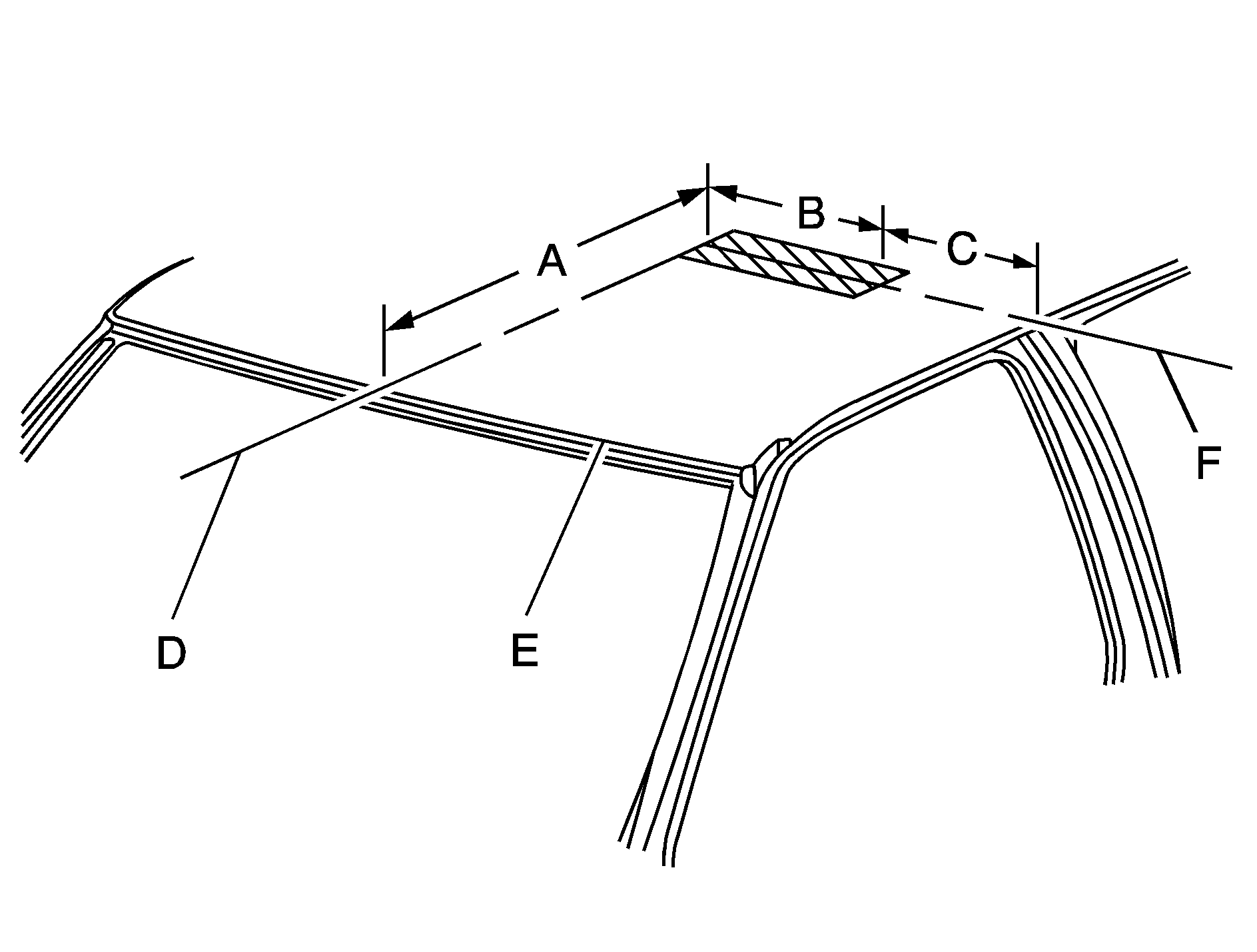
31.81 inches (808 mm)
17.72 inches (450 mm)
9.69 inches (246 mm)
Roof Centerline
Roof Edge
Centerline for Drilled Hole
- Disconnect the negative (-) battery cable at the battery.
- Make the electrical connections using either option A or option B.
Notice: Pulling the wiring harness through a panel hole that has sharp edges may cause damage to the wire and/or wire insulation. Remove sharp edges from the panel hole before pulling the wire through it.
Option A: Roof Wires Directly to Accessory
- Drill a 3/8 inch to 1/2 inch (10 to 13 mm) hole in the outer roof panel in the area shown in the illustration. The hole should only go through the outer panel. Remove all sharp edges from the drilled hole.
- Pull out the wiring harness being careful to avoid scraping the insulation on the edge of the hole.
- Extend the wiring harness to the accessory.
- Connect the brown wire to the accessory hot terminal.
- Connect the black wire to the accessory ground terminal.
- Cover the hole in the roof with a durable sealant such as silicone rubber sealer.
Option B: Use Wiring Harness Package 12150250. Obtain from GM Service Parts through the GM Dealership
- Drill a 1.25 inch (32 mm) hole in the outer roof panel in the area shown. The hole should only go through the outer panel. Remove all sharp edges from the drilled hole.
- Pull out the wiring harness being careful to avoid scraping the insulation on the edge of the hole.
- Cut the wire to length. Install terminals to wire ends and insert into the connector. The brown wire goes in cavity A and the black wire in cavity B. Push in the secondary lock to retain the wires.
- Attach the harness assembly from the package to the accessory. Cover with the supplied conduit for added protection. Connect the orange wire to the accessory hot terminal and the black wire to the ground.
- Complete the connection from the roof harness to the extension harness. Cover the mated connector with the supplied foam. Push the foam covered connection and excess wire through the roof panel hole.
Restoring Power

The auxiliary lamp switch is located on the center of the instrument panel near the climate controls.
This switch includes wiring provisions for a dealer or a qualified service center to install an auxiliary roof lamp. When the switch wiring is connected to an auxiliary roof mounted lamp, pressing the switch will activate the lamp and illuminate an indicator light near the switch. Pressing the switch again will turn off the roof mounted lamp.
- Be sure that the auxiliary lamp switch is off.
- Vacate the vehicle and reconnect the battery cable.
- Turn the auxiliary lamp switch on. The accessory should now be working. If it is not working, check the connections.
- After ensuring that the accessory is working properly, install the grommet in the hole. Seal with silicone sealer to prevent water leakage.
Notice: Overloading the vehicle's electrical system may damage your vehicle's accessories. Do not overload the vehicle's system by having unnecessary accessories on at the same time.
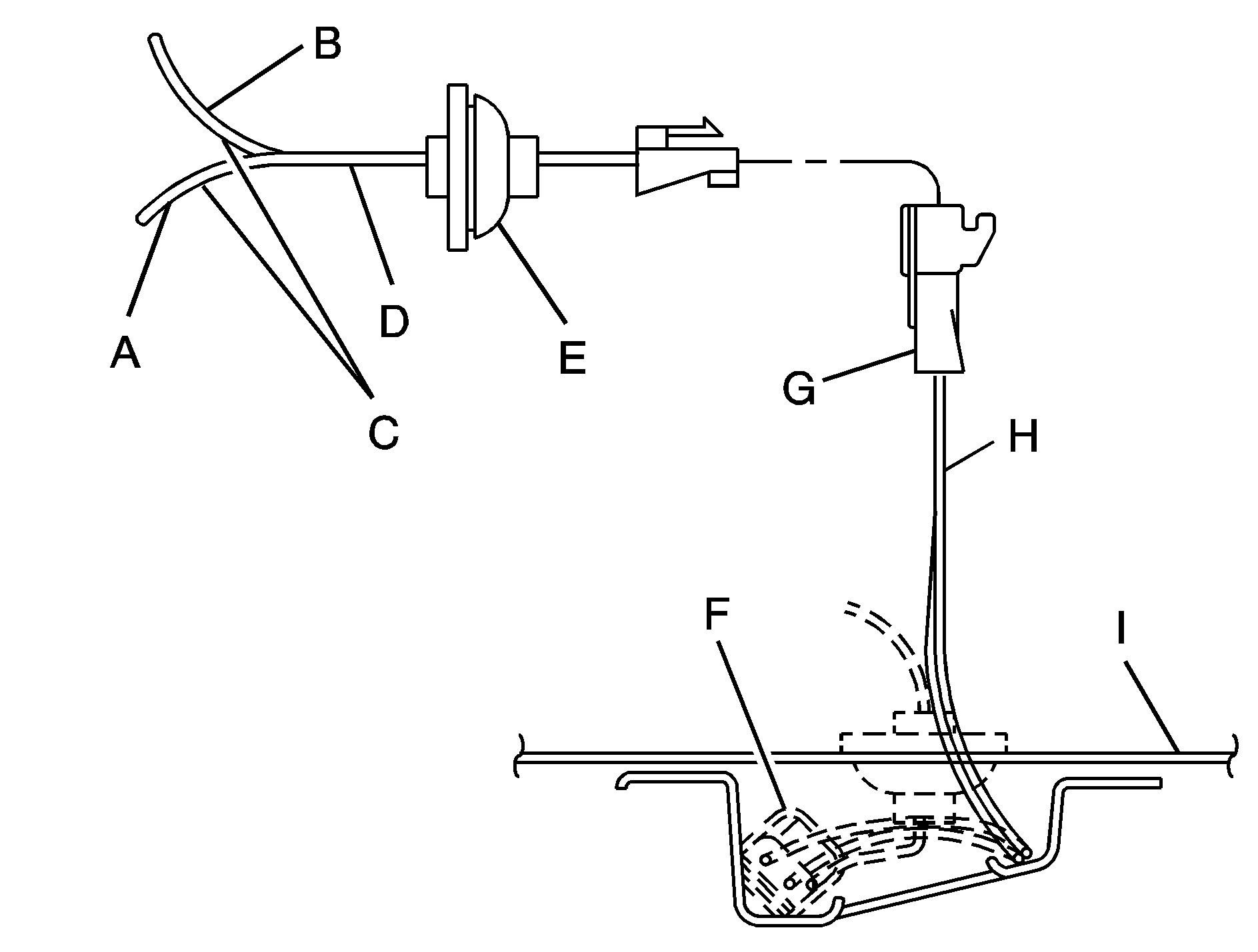
Option B

Black Wire
Orange Wire
To Roof Mounted Lamp
Harness Assembly
Grommet (Roof)
Foam Insulator (Adhesive-Backed)
Harness Connector, Secondary Lock and Terminal
Brown Black Wire
Vehicle Outer Roof Panel
Maintenance
The circuit is fed from the #2 post on the underhood electrical center and protected by the fuse labeled #2 post located in the electrical center. Always replace the fuse with a 30 amp maxi-fuse.
