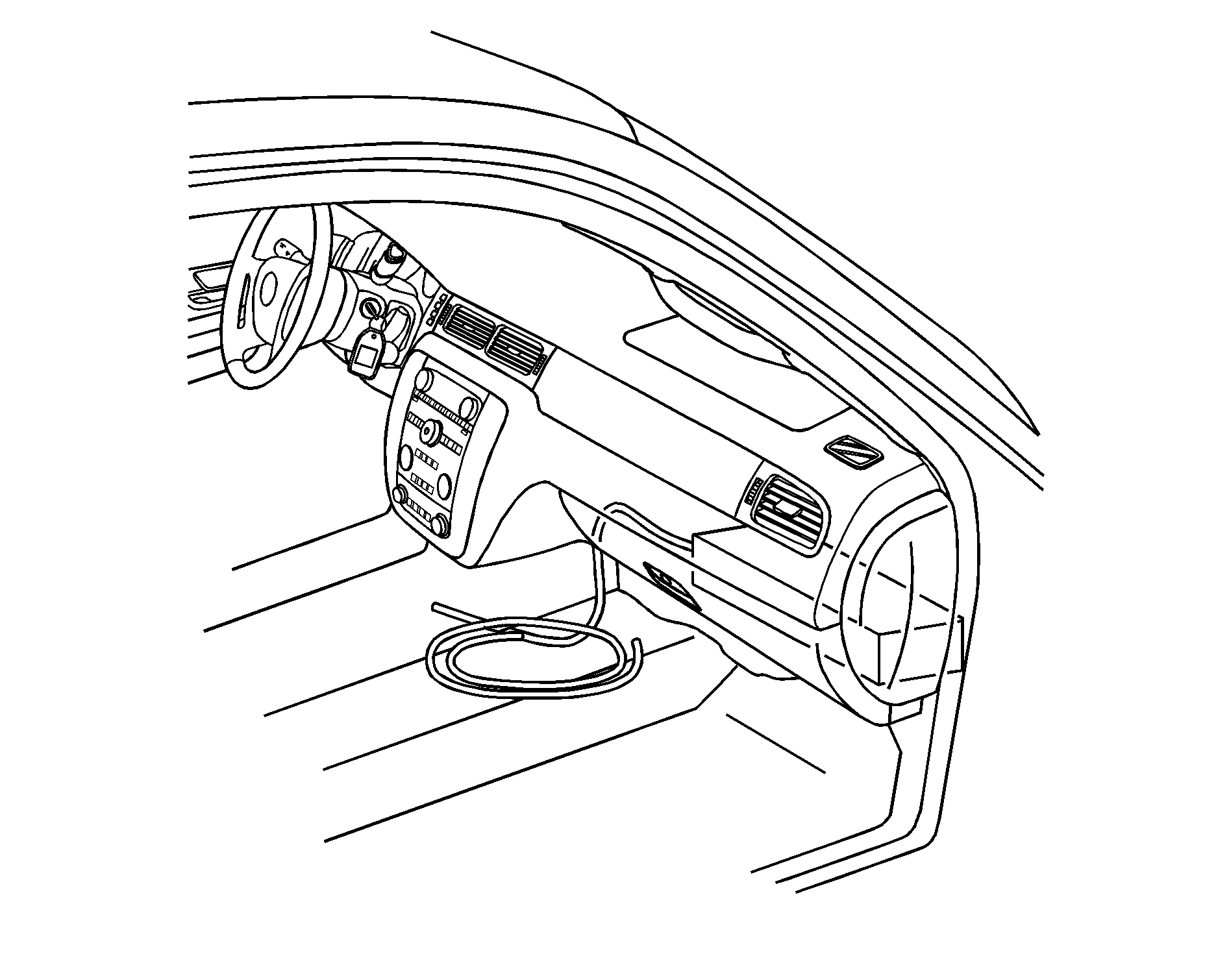
Wiring Provisions - 12-Volt Battery Power
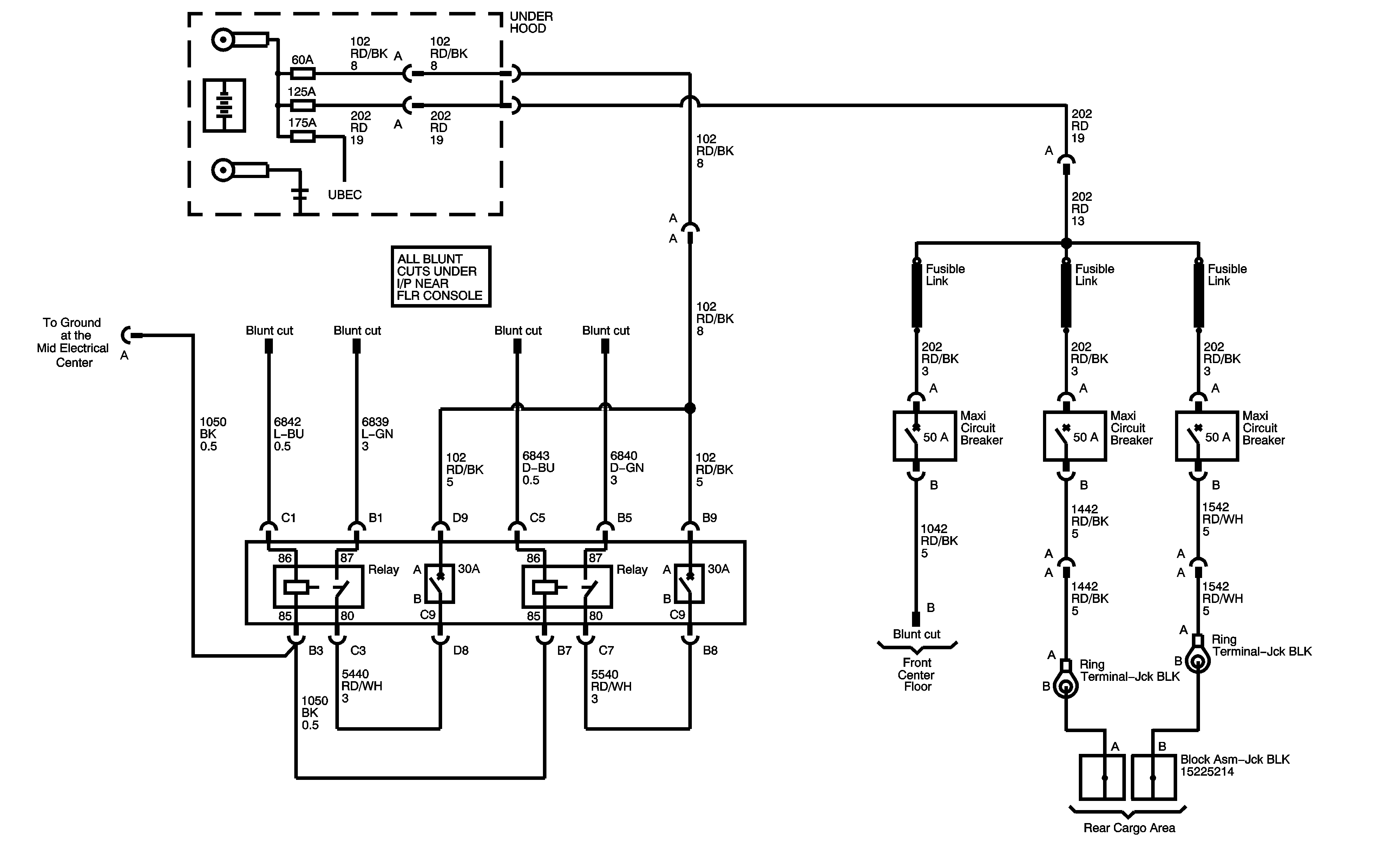
The vehicle is equipped with wiring provisions for a 12-volt battery power supply. Refer to the following information when adding electrical accessories that will use the 12-volt power supply feeds connected to the vehicle's electrical system. The wiring harness is located below the instrument panel near the center of the vehicle. The following information describes the breaker and relay location and provides a wiring diagram to aid in connecting customer equipment.
Electrical Connections
Notice: Before modifying or adding any wiring, be sure that it will work properly with your vehicle's wiring system. Because there are so many modifications that can be made for many different bodies and accessories, GM cannot take responsibility for any changes made. Such changes may not be covered by your GM Warranty. Have the work done by an experienced electrical technician.
All wiring must be properly protected by fuses, etc. and must be routed properly so that it will not be cut, pinched or rubbed by other parts of the vehicle. Do not route wiring in areas where it will be very hot. Be sure not to overload the vehicle's wiring, connectors and components. All added wire must be at least the same size as the wire being attached to for proper fuse protection.Installation Instructions -- 12-Volt Accessory Power Supply
- Disconnect the negative (-) battery cable at the battery. The negative (-) battery cable must be disconnected before the positive wiring lead is connected to the power accessory.
- Locate the power supply harnesses, one under the instrument panel near the center of the vehicle, and one within the driver side rear cargo area jack stowage compartment.
- Prepare the wires that are to be used to connect the power accessory. Do not remove the unused wires. Tape unused wires back in their original position under the instrument panel.
- Complete the wiring installation of the customer added accessory with additional wire required for the specific electrical accessory power connection. The wire gauge, 12 gauge (3.0 mm²), should be the same as the wiring of the installed harness.
- The ignition must be turned to OFF prior to attaching the cables to the battery, or serious damage to the Body Control Module (BCM) may result.
- Reconnect the negative (-) battery cable to the battery. Torque the bolt to 3.6 lb-ft. (5 N·m).
- Reset the clock time and radio pushbuttons as desired.
The windshield wiper switch and the radio must be turned off before attaching cables to the battery.
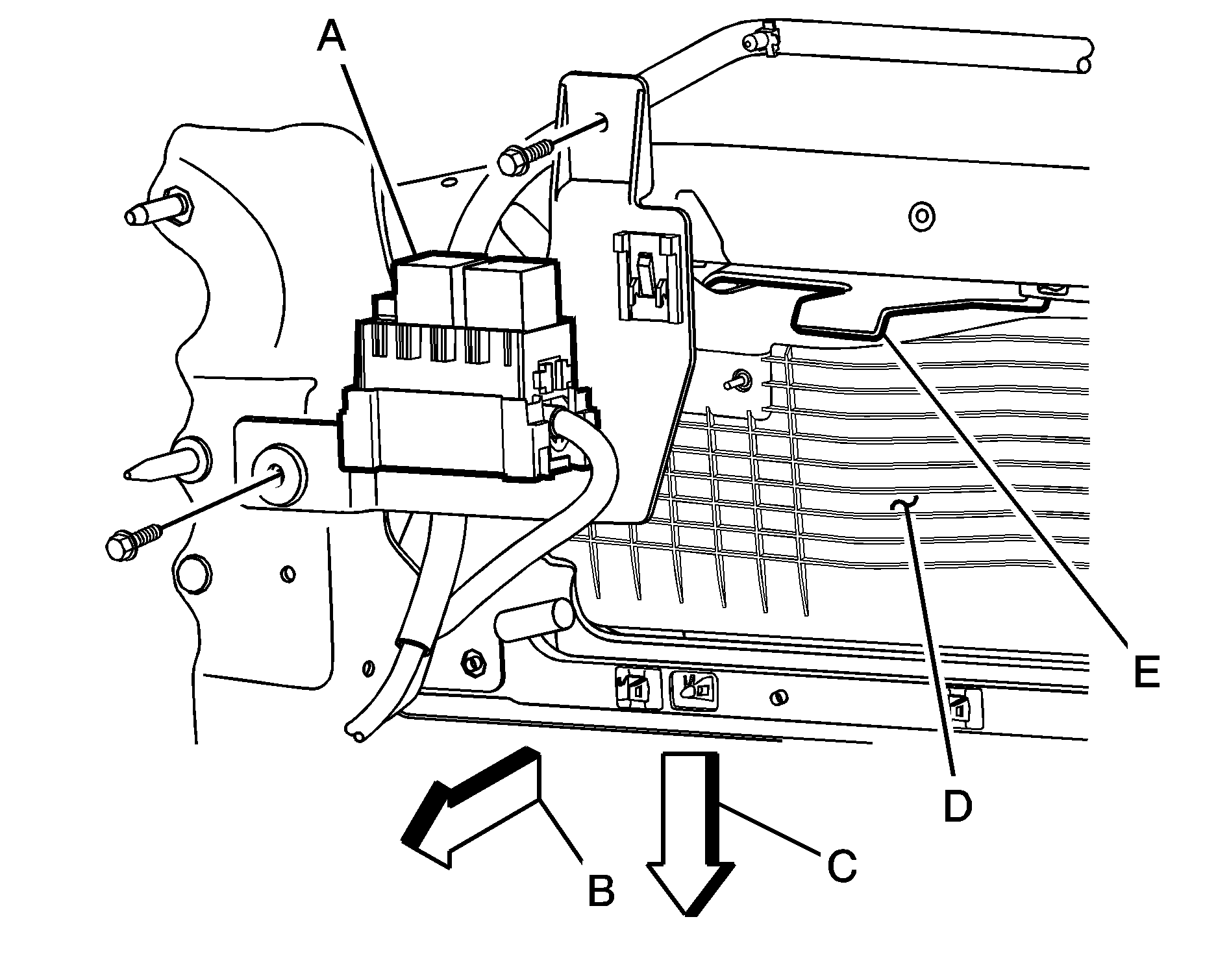
The 12-volt battery power is supplied through two underhood mega fuses, one 125 amp and one 60 amp. This underhood power is fed to the breaker/relay center via a harness that passes through the driver side front of the dash, and routes across the instrument panel to a position forward of the glove box. The breaker/relay center is mounted to the instrument panel structure forward of the glove box. The center includes a plastic bracket, two relays, two 30 amp breakers and three 50 amp mega circuit breakers.
Two 30 amp breakers supply power from the underhood 60 amp mega fuse through the contacts of the control relays to 12 gauge (3.0 mm²) blunt cut wires. These two blunt cut leads are part of wire coil under the instrument panel near the center of the vehicle.
Each relay is operated by a 20 gauge (0.5 mm²) blunt cut, light or dark blue control lead included in the 4 foot (122 cm) loop of wire coiled under the instrument panel.
Three 50 amp mega circuit breakers, protected by three fusible links, supply power directly from the underhood 125 amp mega fuse through three, 10-gauge wires (5.0 mm²) wires. Two of the wires are routed through the body harness to buss junction blocks in the left rear of the cargo area and secured near the jack and tools. This 4 foot (122 cm) of coiled wires can be accessed by removing the cup holder on the top of the trim panel. The third 10-gauge (5 mm²) wire is a blunt cut lead which is part of the 4 foot (122 cm) loop of wire coiled under the instrument panel near the center of the vehicle.
An 8-gauge (8 mm²) ground lead is also provided, and it is located under the front passenger sill plate. It can be accessed by removing the sill plate and pulling the loop of wire at the front of the plate. The lead is 4 feet (122 cm) long.
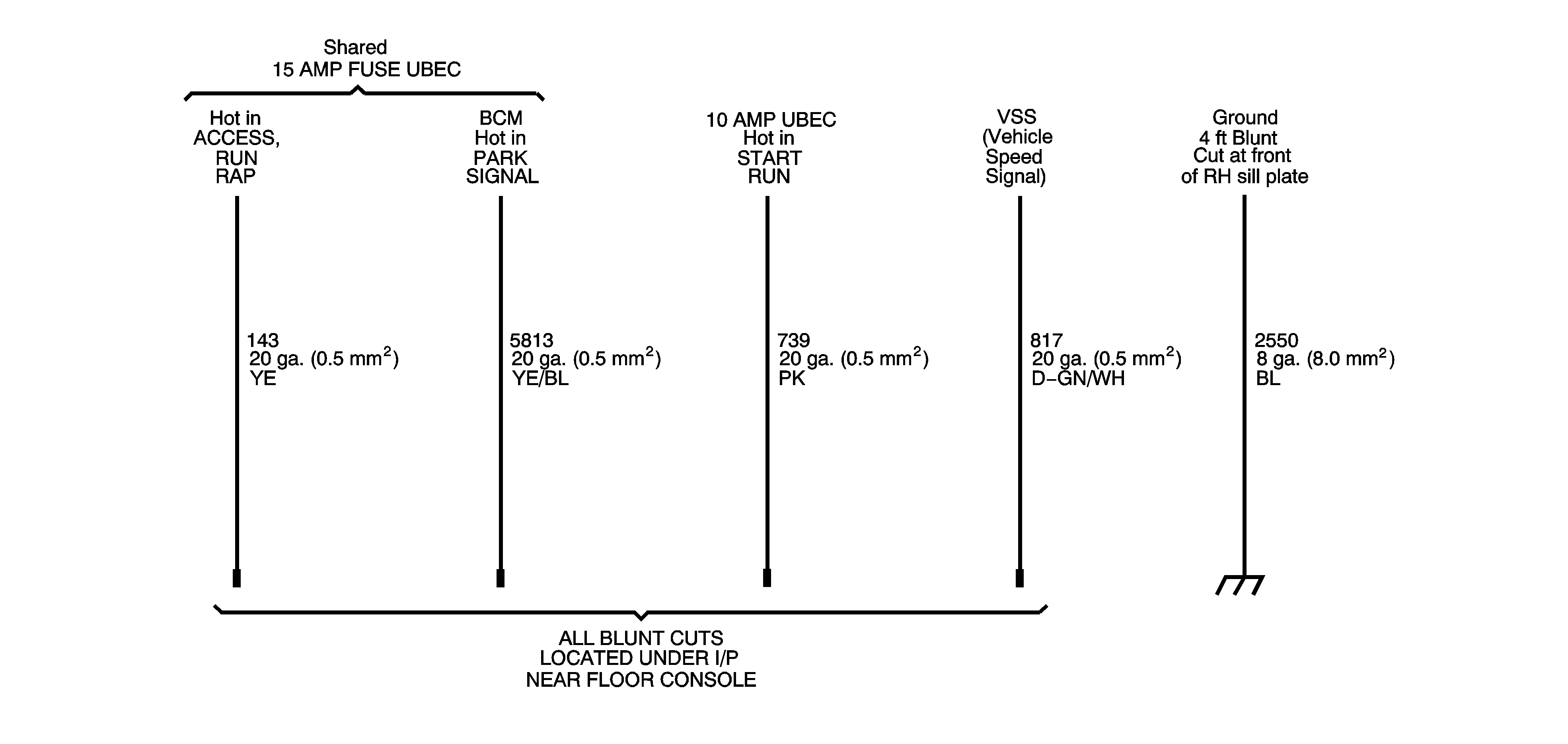
Blunt cut ignition controlled power and signal circuits are also included in the wire coiled under the instrument panel near the center of the vehicle. They include:
| • | *A yellow, 20 gauge (0.5 mm²) circuit, Hot in ACCESSORY, RUN or RAP (Retained Accessory Power). |
| • | A pink, 20 gauge (0.5 mm²) circuit, Hot in START and RUN. (7A maximum load) |
| • | *A yellow/black, 20 gauge (0.5 mm²) transmission park signal. The circuit provides switched power when the transmission is in P (Park) and the engine is running. |
| • | A dark green/white, 20 gauge (0.5 mm²) Vehicle Speed Signal (VSS) provides 4,000 pulses per mile. |
*These two circuits share a 15 amp fuse. (10 amp combined maximum load)
Servicing Relays and Fuses
Fuse/Relay Center
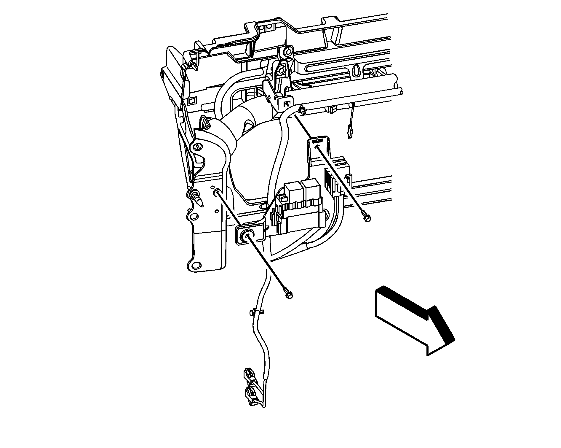
Enlarged View of the Fuse Block
Relays and Circuit Breakers
Front of the Vehicle
Floor of the Vehicle
Glove Box
Tab
The following information tells how to access the vehicle's relay and breaker center for checking and replacing breakers.
The breaker and relay center is located behind and above the instrument panel storage compartment. Remove contents from the storage tray. Using the tab at the back of the compartment, drop the tray down gently toward the floor. It will hang from the hinge. The breaker/relay center is located above the right rear corner of the storage compartment. The bracket is attached to the instrument panel structure with two screws.
Replace a 30 amp circuit breaker with GM Part No. 12182117 circuit breaker, or equivalent. Replace a relay with a GM Part No. 12193604 relay, or equivalent. Replace a 50 amp circuit breaker with a GM Part No. 15319848 circuit breaker, or equivalent.
Reinstall the storage tray into the compartment by lifting it into the instrument panel.
