For 1990-2009 cars only
Radiator Surge Tank Outlet Hose/Pipe Replacement HP2
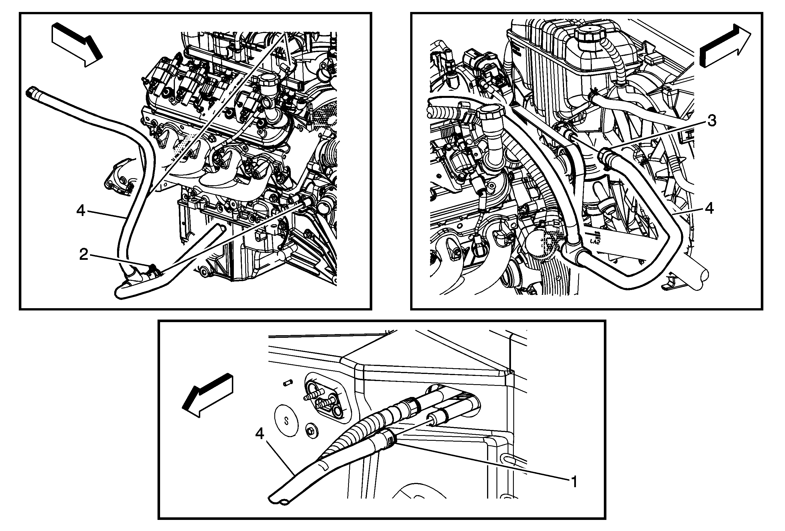
Callout | Component Name |
|---|---|
Preliminary Procedure
| |
1 | Radiator Surge Tank Outlet Hose Quick Disconnect Procedure
|
2 | Radiator Surge Tank Outlet Hose Clamp ProcedureUsing J 38185 reposition the radiator surge tank outlet hose clamps. Special ToolsJ 38185 Radiator Surge Tank Outlet Hose Clamp |
3 | Radiator Surge Tank Outlet Hose Quick Disconnect Procedure
|
4 | Radiator Surge Tank Outlet Hose Tip |
Radiator Surge Tank Outlet Hose/Pipe Replacement 4.8L, 5.3L, and 6.0L Engines
Special Tools
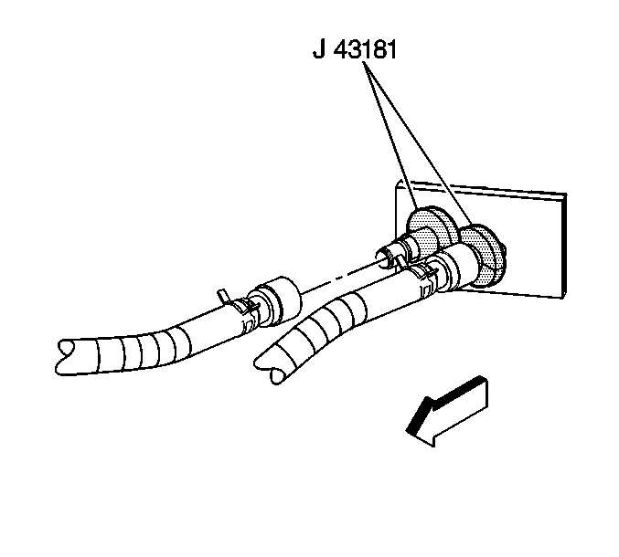
J 43181 Heater Line Quick Connect Release Tool
Removal Procedure
- Drain the cooling system. Refer to Cooling System Draining and Filling.
- Loosen the air cleaner outlet duct clamps at the following locations:
- Remove the air cleaner outlet duct.
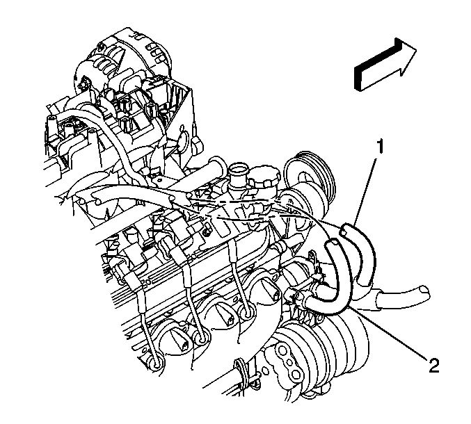
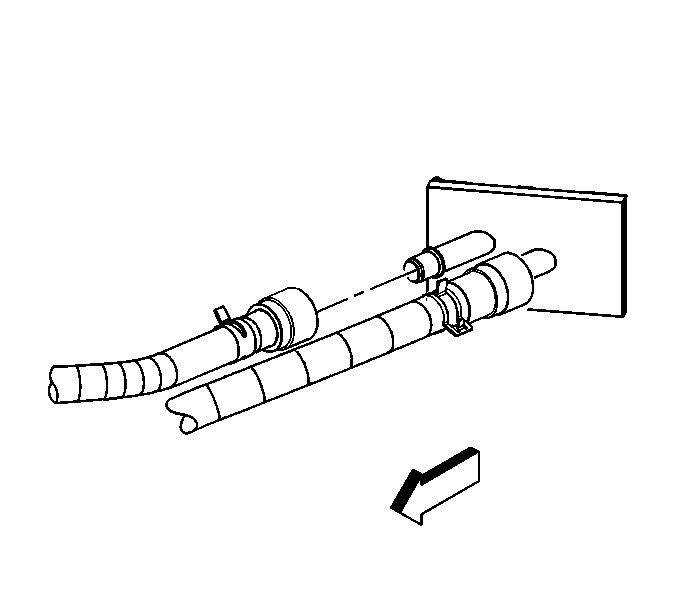
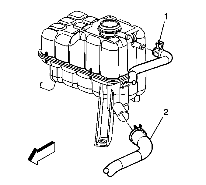
- If equipped without regular production option (RPO) C36 auxiliary heater, remove the surge tank/heater outlet hose (1) from the mounting clip.
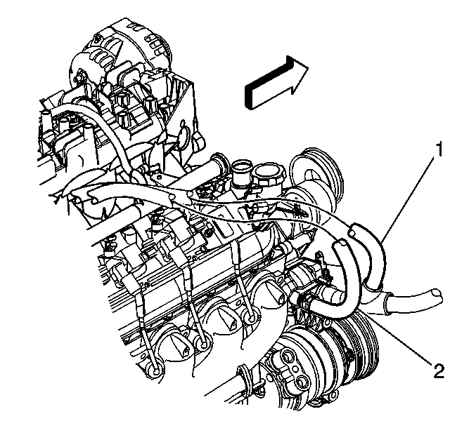
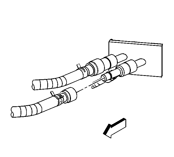
- If equipped with RPO C36 auxiliary heater, remove the surge tank/heater outlet hose (1) from the mounting clip.
- Install the J 43181 to the surge tank outlet hose (black connector).
- Close the J 43181 around the surge tank outlet hose.
- Firmly pull the J 43181 into the quick connect end of the outlet hose.
- If equipped without RPO C36 auxiliary heater, firmly grasp the outlet hose. Pull the outlet hose in order to disengage the hose from the heater and blower module.
- If equipped with RPO C36 auxiliary heater, firmly grasp the outlet hose. Pull the outlet hose in order to disengage the hose from the heater and blower module.
- Reposition the surge tank outlet hose clamp at the surge tank.
- Remove the surge tank outlet hose (2) from the surge tank.
- Reposition the surge tank outlet hose clamp at the water pump.
- Remove the surge tank outlet hose from the water pump.
- Remove the surge tank outlet hose.
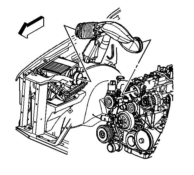
| • | Throttle body |
| • | Mass airflow/intake air temperature (MAF/IAT) sensor |
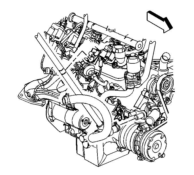
Installation Procedure
- Install the surge tank outlet hose.
- Install the surge tank outlet hose to the water pump.
- Position the surge tank outlet hose clamp to the water pump.
- Install the surge tank outlet hose (2) to the surge tank.
- Position the surge tank outlet hose clamp to the surge tank.
- If equipped with RPO C36 auxiliary heater, connect the surge tank outlet hose to the heater and blower module.
- If equipped without RPO C36 auxiliary heater, connect the surge tank outlet hose to the heater and blower module.
- If equipped with RPO C36 auxiliary heater, install the surge tank/heater outlet hose (1) to the mounting clip.
- If equipped without RPO C36 auxiliary heater, install the surge tank/heater outlet hose (1) to the mounting clip.
- Install the air cleaner outlet duct.
- Align the arrow at the throttle body end of the duct with the throttle body attaching stud.
- Tighten the air cleaner outlet duct clamps at the following locations:
- Fill the cooling system. Refer to Cooling System Draining and Filling.


Firmly push the hose onto the heater and blower module pipe until an audible click is heard.


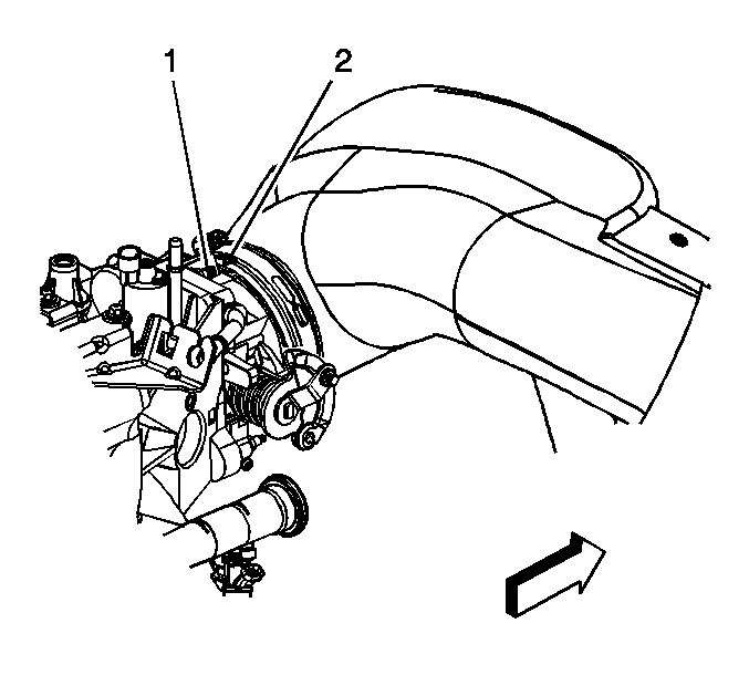
Caution: Refer to Fastener Caution in the Preface section.
| • | Throttle body |
| • | MAF/IAT sensor |
Tighten
Tighten the clamps to 7 N·m (62 lb in).
