Removal Procedure
- Perform the high voltage disabling procedure. Refer to High Voltage Disabling.
- Remove the air cleaner resonator outlet duct. Refer to Air Cleaner Resonator Outlet Duct Replacement.
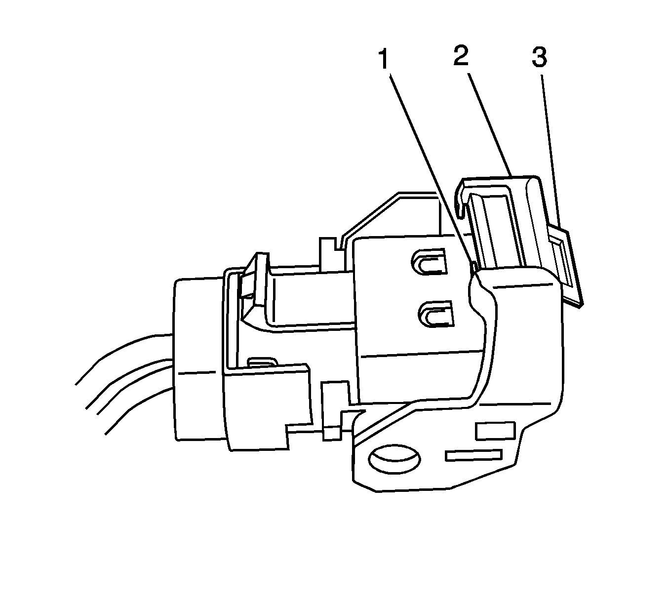
- Release the power steering assist motor electrical harness connector position assurance tab (3).
- Press down on the connector cam lever lock tab (2).
- Push the connector cam lever (3) toward the rear of vehicle.
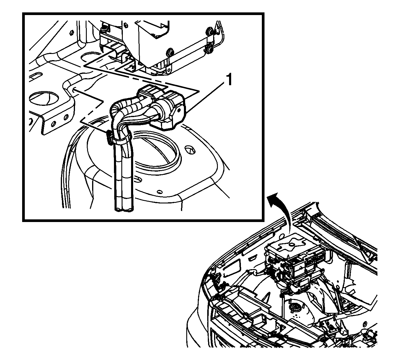
- Separate the power steering assist motor electrical harness retainers from the electronic power steering control module bracket and disengage the electrical connectors (1).
- Remove the engine shield. Refer to Engine Shield Replacement.
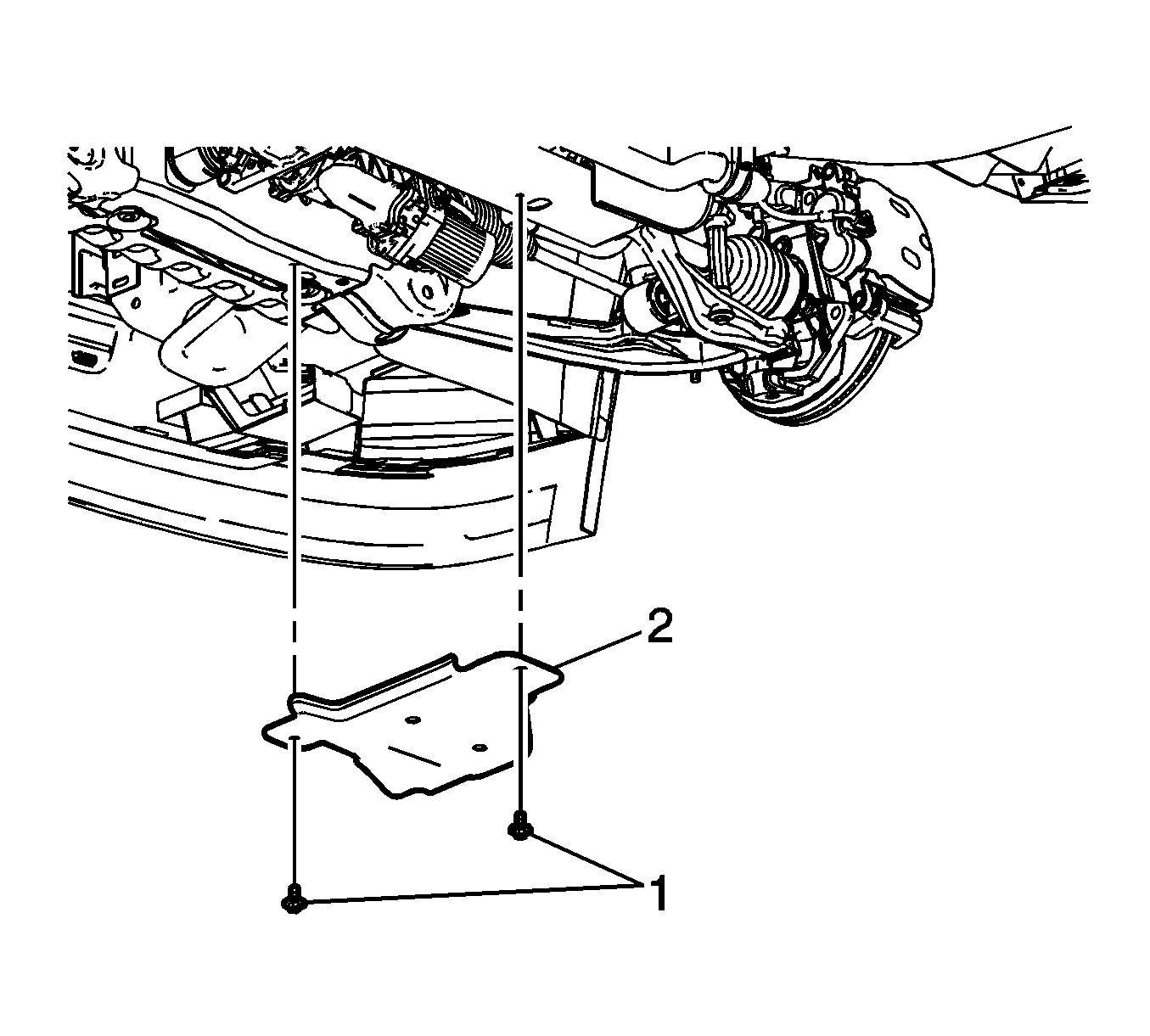
- Remove the steering linkage shield bolts (1) and the steering linkage shield (2).
- Separate the power steering assist motor electrical harness retainers from the frame of the vehicle.
- Pull the power steering assist motor electrical harness through the engine compartment to the bottom of the vehicle.
- Disconnect the power steering assist motor electrical connector at the torque sensor.
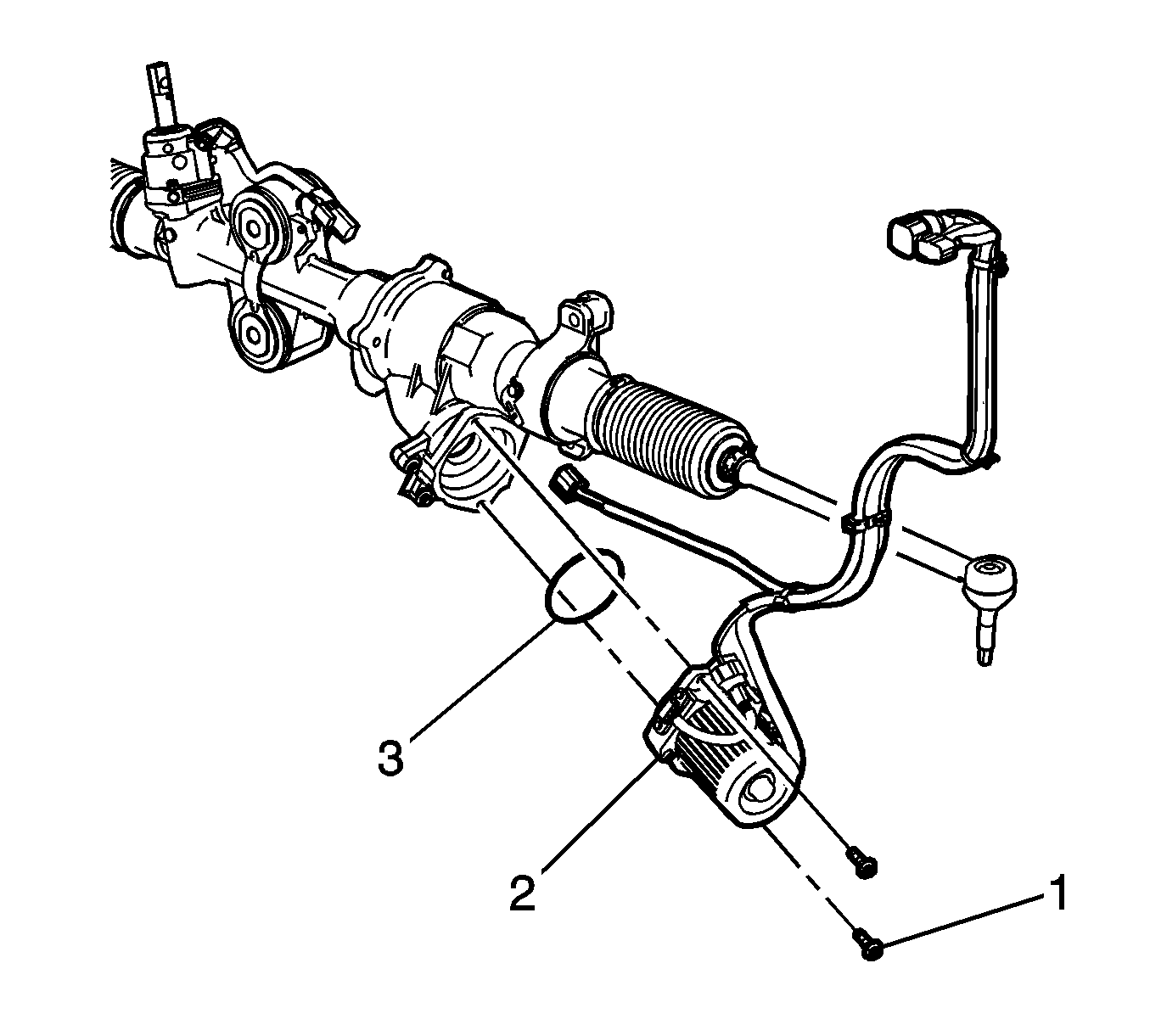
- Remove the power steering assist motor bolts (1).
- Remove the power steering assist motor and electrical harness (2).
- Remove and ensure the power steering assist motor seal (3) is kept protected while out of the vehicle as it will be needed for reinstallation.
Danger: Always perform the High Voltage Disabling procedure prior to servicing any High Voltage component or connection. Personal Protection Equipment (PPE) and proper procedures must be followed.
The High Voltage Disabling procedure will perform the following tasks:| • | Identify how to disable high voltage. |
| • | Identify how to test for the presence of high voltage. |
| • | Identify condition under which high voltage is always present and personal protection equipment (PPE) and proper procedures must be followed. |
Note: The wiring harness protective cover is intended to keep the wiring harness connectors contaminant free. Do not remove the protective cover from the power steering wiring harness extension harness connectors until the harness has been routed to the correct position.

Note: The power steering assist motor harness is not repairable. Only replace the harness and never attempt to repair it.
The connector in the graphic is shown upside down for clarity.
Note: The connector will back off of the electronic power steering control module smoothly as the connector cam lever moves towards it. Do not pull on the connector until it is fully disengaged.

Note: Note the routing and any mounting points for the power steering assist motor electrical harness. Also note any other electrical harnesses that will need to be re-secured to it after installation. Use new retainers and tie straps as needed.


Note: Only remove the 2 bolts indicated in the graphic. Under NO circumstances are the power steering assist motor housing bolts to be removed or loosened. If two or more of these bolts are removed or loosened the steering gear will need to be replaced because the steering gear housing to gear lash will be out of specification.
Note: DO NOT remove the power steering assist motor electrical harness from the power steering assist motor. They are serviced as a unit only.
Installation Procedure
- Install any new wiring harness retainers as needed.
- Position the power steering assist motor (2) and seal (3) to the steering gear.
- Install the power steering assist motor bolts (1).
- Connect the power steering assist motor electrical connector at the torque sensor.
- Route the power steering assist motor electrical harness back through the engine compartment to its previous position and secure the lower part of the wiring harness to the frame.
- Install the steering linkage shield (2) and the steering linkage shield bolts (1).
- Engage the power steering assist motor electrical harness connectors (1) to the electronic power steering control module.
- Ensure the connector cam lever (3) and the connector cam lever lock tab (2) are fully engaged.
- Secure the power steering assist motor electrical harness connector position assurance tab (3).
- Install the engine shield. Refer to Engine Shield Replacement.
- Install the air cleaner resonator outlet duct. Refer to Air Cleaner Resonator Outlet Duct Replacement.
- Perform the high voltage enabling procedure. Refer to High Voltage Enabling.
- Perform the power steering control module setup procedure. Refer to Power Steering Control Module Programming and Setup.

Note: It may be necessary to rotate the front tire and wheel assembly while installing the power steering assist motor to in order for it to mesh with the steering gear properly.
Caution: Refer to Fastener Caution in the Preface section.
Tighten
Tighten the bolts to 13 N·m (115 lb in).

Tighten
Tighten the bolts to 12 N·m (106 lb in).

Note: The power steering assist motor electrical harness connector should engage smoothly as it is pushed on. Do NOT force the electrical connector.

The connector in the graphic is shown upside down for clarity.
